Control the Flashing Rate of An Led Using A Potentiometer
- nithya7rns
- Dec 22, 2020
- 8 min read

Updated: Sep 22, 2024
Flashing of LED is usually used in #signaling applications. Let's say we are driving to the Supermarket in our car and want to park it in a very small place available since we were late. We have a parking sensor that will guide us with the distance between the wall and our car. At the same time, if we observe, we see the LED lights present on the side of the car as indicators start blinking at a faster rate when we start nearing the wall.
So here the Flashing of the LEDs along with the #buzzer tone is used for signaling. This is just one of the many applications of Flashing LEDs at a varying rate. Let us now learn how the circuit behind this designed and how it works. We start with the list of components required.
In this article, we are going to design the circuit using two different #microcontrollers. One circuit with Arduino and the other using NodeMCU. So when we are going to describe the working of the circuit, the article will be divided into two based on the type of microcontroller used. But the list of Hardware required will be the same except the microcontrollers which will be separately used for each of the two circuits. Here we go.
Hardware Requirements
Arduino UNO
Develop a stronger concept in Arduino through this article:- What is Arduino?

Arduino board is a microcontroller that is used to accept inputs from sensors connected and provide an output action on the desired device connected to it. The sensor inputs can be that from light-detecting sensors, flame sensors, temperature sensors, etc. The output function done by the devices can be turning on an LED, the sound of a buzzer, or a Serial monitor display.
Buy Arduino UNO from here.
2. NodeMCU

NodeMCU is a platform provided for #IoT. It basically includes firmware (computer software that contains instructions and controls the hardware) which runs on Esp8266 WiFi SoC (software on-chip). It is open-source firmware available for prototyping and developing kits. MCU means a Micro-Controller Unit. The device contains GPIO (General Purpose Input Output) pins which send and receives data on connection to other devices.
The specifications of the Esp12e module are:
32-bit lx106 RISC Microprocessor.
80MHz-160MHz, the adjustable clock frequency.
Supports Arctic OS(Operating System).
1 KB Internal RAM.
4 MB External flash.
2.5V to 3.6V, 3.3V onboard.
600 milliAmp Regulator.
80 milliAmp Operating Current.
20 microAmp Current in sleeping Mode.
17 GPIO pins (which include ADC channels, 2 UART Interfaces, 4 PWM outputs, LED, Reset button, etc.).
Buy NodeMCU from here.
NOTE: We don't require both Microcontrollers for building one circuit. The circuit designs are done separately and are explained further in the Article.
3. LED
Build your technical concepts in LED by this article:- Light Emitting Diode

Light Emitting Diode is a commonly used light source. It is a #semiconductor. When current flows through it, LED emits light.
Buy LED from here.
4. Jumper Wires

These are the main components that are used to establish the connections between different devices of the circuit.
Buy Jumper Wires from here.
5. Resistor

Resistors are passive devices that restrict the flow of current or divide the voltage through the circuit. The resistor used for the proper functioning of this circuit is a 220 Ohm Resistor.
Buy Resistors from here.
6. Potentiometer

A potentiometer is a device that is used for varying resistance in a circuit. It usually consists of three terminals and sliding or rotating contact that further act as an adjustable #voltage divider for the device.
Buy a Potentiometer from here.
7. Breadboard

The breadboard is the basic component of any circuit building process. All components, be it input sensors or output display devices are connected to the Arduino or any other microcontrollers using wired connections through a breadboard. The holes in the breadboard are in series. There are various sizes like full-sized, half-sized, and mini breadboards.
Buy Breadboard from here.
8. Screwdriver

It is basically a tool used for installing or removing the screws that are used in fixing machines, instruments, etc. In this circuit, we are going to use the screwdriver as a handle to control the potentiometer by rotating it.
Buy Screwdriver from here.
Circuit Type 1 - Using Arduino UNO
Circuit connections
The circuit connections for this device is simple to understand.
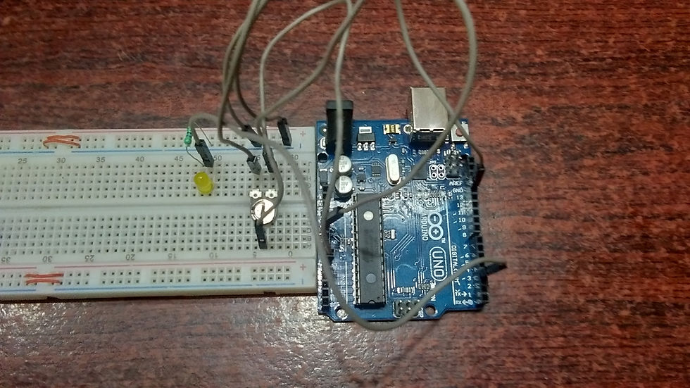
The Positive terminal of the LED is connected to the Digital PIN (3) of the #Arduino. The Negative terminal of the LED is connected to the ground line of the Breadboard through the resistor, which is assigned by connecting the GND terminal of Arduino to the hole of a particular line in the breadboard.
Similarly, another Line of the breadboard is declared as a Power supply line by connecting the 5V terminal of the LED to a hole of a particular line of the Breadboard. There are three terminals of the #Potentiometer. The first terminal is connected to the Power supply line of the Breadboard. The middle/second terminal is connected to the analog PIn (A0) of the Arduino board. The third terminal is connected to the ground line of the Breadboard.
The potentiometer is fitted with the Screwdriver that acts as a handle to control the rotation of the Potentiometer contact. Finally, the Arduino Board is interfaced with the system in which the #IDE is present and the code is written.
Code :
Note: Please change the file format to .ino(Arduino IDE) format before you upload the code to the Arduino board.
Working
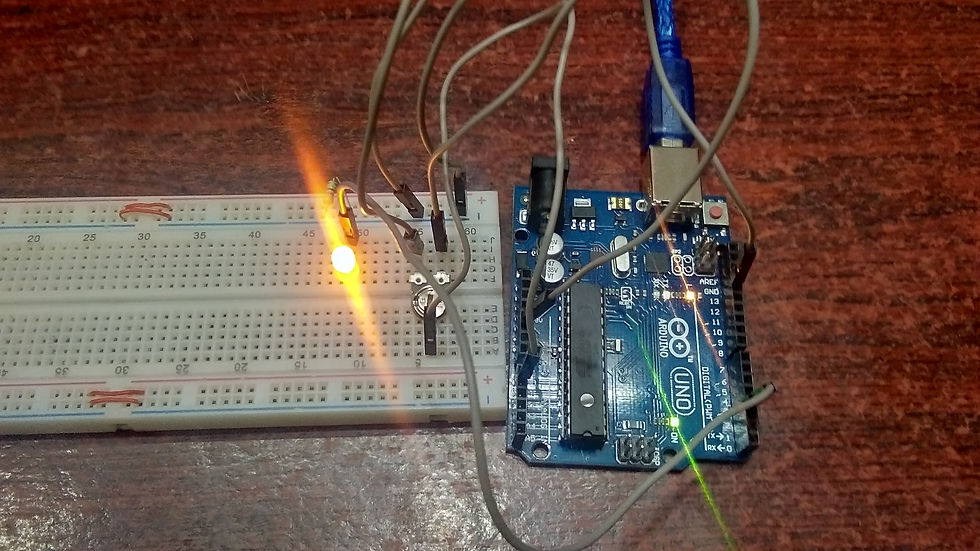
The potentiometer is nothing but a resistive device that produces a continuously variable voltage output that corresponds to the change in the rotating/sliding contacts. In this circuit, the voltage is supplied to the LED from the Arduino board, and control of the supply is with the potentiometer which will send the variable voltage to the LED and causes a change in the #Flashing rate.
Looking at the working, first, the LED is glowing at the beginning of the functioning of the circuit. The potentiometer is being controlled by using a #Screwdriver as a handle. When the resistance is varied, the continuously varying voltage is given as the output of the Potentiometer. This is the Analog data read from the Potentiometer and displayed on the Serial #Monitor.
The amount of output given in terms of the #Analog Data from the Potentiometer decides the delay that is supposed to be given in between every blink or Flash of the LED. So the delay( ) function takes the analog value as a delay. We know that digital values can be only 0s and 1s. But for Analog input/output values the range is from 0 to 1023 showing the Lowest and highest possible values respectively.
The serial monitor will show the values ranging between 0 and 1023 when we rotate the potentiometer contact. So we can state that when the output voltage value from the Potentiometer is high, the higher is the delay and the Flashing rate is slower. When we control the potentiometer to decrease the output value, the delay will be less and the LED blinks at a faster Flashing Rate and every value will be seen as an output on the #Serial Monitor.
The video given below shows an explained version of the circuit building, working of the code, and display of output for better understanding.
Check the Project working video here - Control the Flashing Rate of An Led Using A Potentiometer on Arduino Uno
Project video By - Harshit Gupta
Circuit Type 2 - Using NodeMCU
Circuit connections
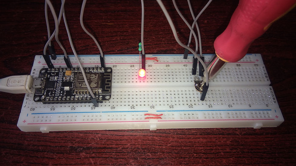
The lines for Ground and Power supply are separately selected on the Breadboard by connecting the Ground terminal and the 5V Power supply to the breadboard respectively.
The positive terminal of the LED is connected to #GPIO PIN 5 of the NodeMCU and the negative terminal of the LED is connected to the ground line of the breadboard through the resistor. The first terminal of the Potentiometer is connected to the ground line of the breadboard. The second/middle terminal is connected to the #ADC (Analog to Digital convertor) of NodeMCU and the third terminal is connected to the 5V power supply line on the breadboard.
The potentiometer is fitted with the Screwdriver that acts as a handle to control the rotation of the Potentiometer contact. Finally, the NodeMCU is interfaced with the system in which the #IDE is present and the code is written.
Code :
Note: Please change the file format to .ino(Arduino IDE) format before you upload the code to the Arduino board.
Working

The potentiometer is nothing but a resistive device that produces a continuously variable voltage output that corresponds to the change in the rotating/sliding contact. In this circuit, the voltage is supplied to the LED from the ESP8266 #NodeMCU board, and control of the supply is with the potentiometer which will send the variable voltage to the LED and causes a change in the Flashing rate.
Looking at the working, first, the LED is glowing at the beginning of the functioning of the circuit. The potentiometer is being controlled by using a Screwdriver as a handle. When the resistance is varied, the continuously varying voltage is given as the output of the Potentiometer. This is the Analog data read from the Potentiometer and displayed on the Serial Monitor.
The amount of output given in terms of the Analog #Data from the Potentiometer decides the delay that is supposed to be given in between every blink or Flash of the LED. So the delay( ) function takes the analog value as a delay. We know that digital values can be only 0s and 1s. But for Analog input/output values the range is from 0 to 1023 showing the Lowest and highest possible values respectively.
The serial monitor will show the values ranging between 0 and 1023 when we rotate the potentiometer contact. So we can state that when the output voltage value from the Potentiometer is high, the higher is the delay and the Flashing rate is slower. When we control the potentiometer to decrease the output value, the delay will be less and the LED blinks at a faster Flashing Rate and every value will be seen as an output on the Serial Monitor.
The video given below shows an explained version of the circuit building, working of the code, and display of output for better understanding.
Project video By - Harshit Gupta
The Flashing rate project is easy to understand, but at the same time it is has a high application rate. By this, we mean that it has been implemented in many devices and circuits. As discussed, this circuit is usually used for signaling purposes. Signaling is not only in vehicles, it can also be in Circuitry boards like Arduino, where the built-in LED flashes when the code is being uploaded to the board and stops when it is complete. Similarly, there are many applications. Find out more and use this circuit on your own devices. Kudos!!
SEE ALSO:
Order Electronics Projects
Want us to guide you through your project or make the project for you? Click on the button below or reach out to us via Call/WhatsApp at (+91) - 7600948607
You can -
Order Basic Electronics Projects
Order Embedded Systems Projects
Order IoT Projects
Order FPGA Projects
Order VLSI Projects
Order Image Processing Projects
Order Matlab Projects
Order TinkerCAD Projects
Order Proteus Projects
Click on the button below to fill out the project inquiry form -
Create Various Projects
Check out our Free Arduino Projects Playlist - Arduino Projects
Check out our Free Raspberry Pi Projects Playlist - Raspberry Pi Projects
Check out our Free TinkerCAD Projects Playlist - TinkerCAD Projects
Check out our Free IoT Projects Playlist - IoT Projects
Check out our Free Home Automation Projects Playlist - Home Automation Projects
Check out our Free NodeMCu Projects Playlist - NodeMCu Projects
Follow us -
Please do follow us i.e. #learnelectronicsindia to get daily updates about new blogs, videos, courses, products, offers, competitions, quizzes, and Internship Opportunities.
Informative and concise! LearnElectronics India always delivers quality content.
What a gem of an article! I stumbled upon this blog by Learn Electronics India while searching for ways to control LEDs with a potentiometer. The content was so engaging, and the explanations were on point. This tutorial not only helped me grasp the core concept but also inspired me to learn more about electronics. Thanks for sharing this valuable resource.
Great share, thanks for posting