Controlling the brightness of an LED with Raspberry Pi | PWM
- Usha Saha

- Aug 22, 2020
- 4 min read
Updated: Sep 27, 2024
Through this article, Controlling the brightness of an LED with Raspberry Pi using PWM, one would learn how the brightness of an led can be controlled using the PWM signal. Here #PWM stands for Pulse Width Modulation. This is a technique that can be used to control the speed of a #dc motor or the #brightness of an led or controlling the #servo motor.
Elements used
The image shows the list of components needed. Let's have a quick peek at each of them.

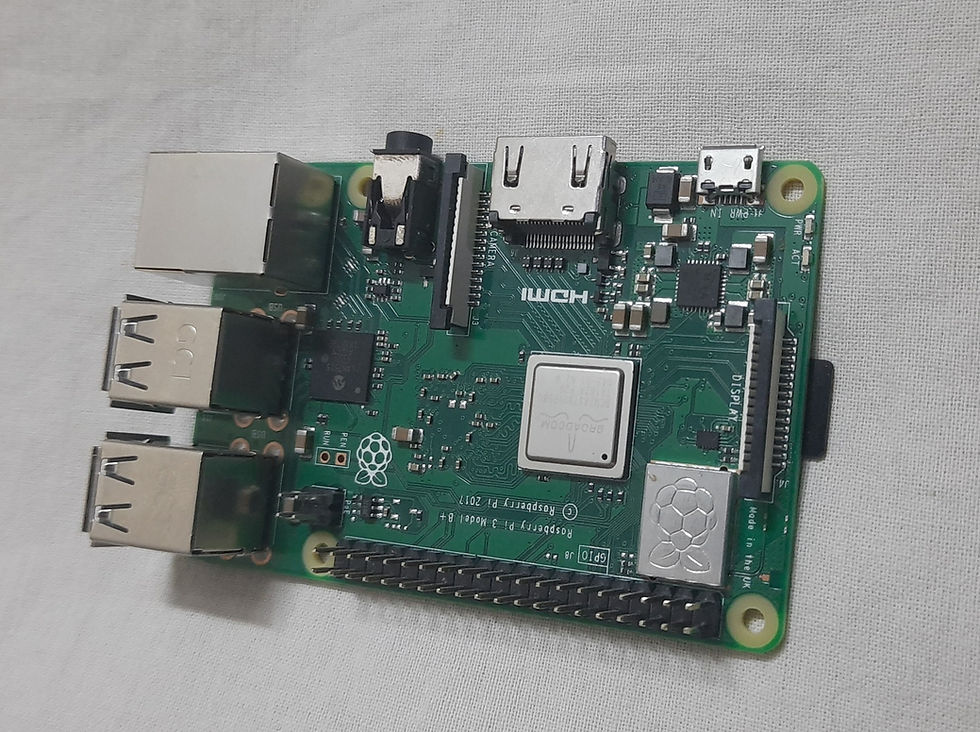
Raspberry Pi 3 Model B+
The Raspberry Pi is a series of small single-board computers. Here 3 Model B+ indicates the generation of the RPi board. The Raspberry Pi is also written as RPI or RPi or Raspberry Pie. The Raspberry Pi Model B+ is of the nearby size of a credit card.
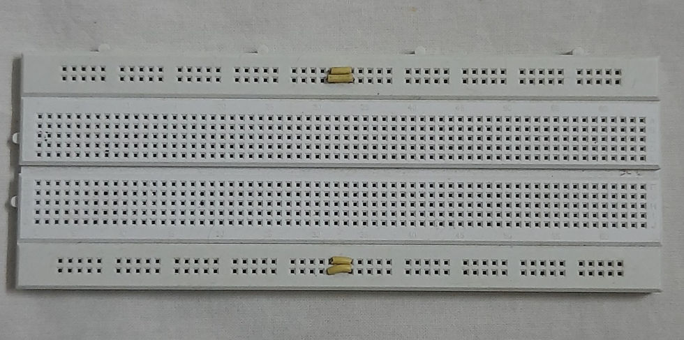
Bread Board:- A breadboard is a rectangular board with small holes in it which are used for connecting elements. The connections are not fixed and can be varied. In a breadboard, all the holes in one horizontal line are in series connection with each other. Breadboards are made from plastic and come in all shapes, sizes, and even different colors, the most common sizes are "full-size," "half-size," and "mini" breadboards.
Jumper wires:- Jumper wires are used to establish a connection between different elements in the circuit and #Raspberrypi board. There are two types of wire, male and female. The male wires have the ends that can be connected to other ends and the female wires are the ones that have the receiving end.

Resistor:- A 1k resistor used in the circuit is shown below.

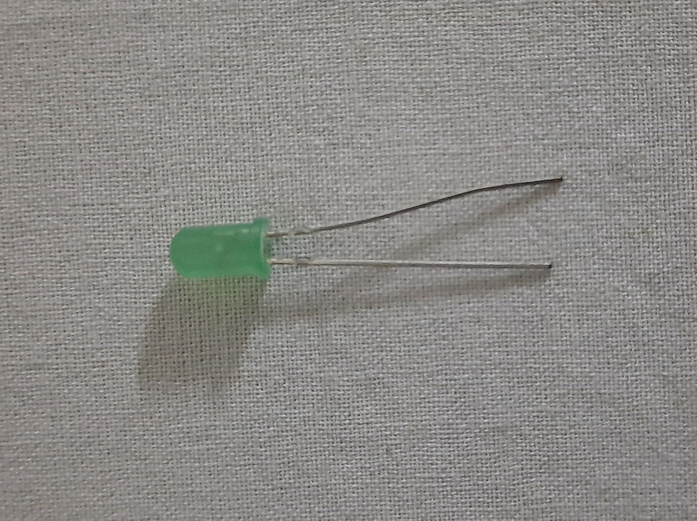
LED:- A Light Emitting Diode is a semiconductor device that emits light when current flows through it.
USB Cable
This cable is used to connect the RaspberryPi to the power supply. It also helps in the transmission of data.

Circuit Diagram
The circuit diagram is as shown below, where the cathode(negative) pin of the led is connected to the ground pin of the Raspberry Pi. Another end of the diode that is the anode(positive) end of the led is connected to one end of the resistor. And the other end of the resistor is connected to the #GPIO pin of the Raspberry Pi. Specifically, GPIO 18 which provides the PWM signals.
Download the code from here
Working
The Raspberry Pi's GPIO gives either 3.3 volts as maximum or zero volts, so the output is a square wave and in order to vary the brightness, we cannot get the voltage between 0-3.3 volts. Therefore here we use the concept of #duty cycle that is the on and off time of the signal and vary the brightness accordingly.

The figure above shows the voltage-time graph with a maximum voltage of 3.3v and a minimum voltage of zero. The thing which is to be noted here is that with the variation of the duty cycle the brightness of an led can be varied with the help of #Pulse Width Modulation(PWM).
As notable from the graph at 100% duty cycle the graph is almost constant whereas at 80% duty cycle in the graph a small T-off time is there, a time where the output is low. Similarly constantly changing the duty cycle changes the T-on and T-off time and thus we can change the brightness of the led.

The images are shown below which shows the variation in the brightness of the led.


Check the Project working video here - How to control LED brightness with Raspberry Pi? | Pulse Width Modulation Dimming LED | RPi Projects
Through this project, one would learn how to control the brightness of an led with the PWM signal. There are many other applications of PWM and with this knowledge, one can explore the same on a DC motor and see how to control the DC motor.
Visit the links below to explore more
Order Electronics Projects
Want us to guide you through your project or make the project for you? Click on the button below or reach out to us via Call/WhatsApp at (+91) - 7600948607
You can -
Order Basic Electronics Projects
Order Embedded Systems Projects
Order IoT Projects
Order FPGA Projects
Order VLSI Projects
Order Image Processing Projects
Order Matlab Projects
Order TinkerCAD Projects
Order Proteus Projects
Click on the button below to fill out the project inquiry form -
Create Various Projects
Check out our Free Arduino Projects Playlist - Arduino Projects
Check out our Free Raspberry Pi Projects Playlist - Raspberry Pi Projects
Check out our Free TinkerCAD Projects Playlist - TinkerCAD Projects
Check out our Free IoT Projects Playlist - IoT Projects
Check out our Free Home Automation Projects Playlist - Home Automation Projects
Check out our Free NodeMCu Projects Playlist - NodeMCu Projects
Follow us -
Please do follow us i.e. #learnelectronicsindia to get daily updates about new blogs, videos, courses, products, offers, competitions, quizzes, and Internship Opportunities.
What a fantastic blog! Learn Electronics India really knows how to explain technical concepts in a way that's easy to grasp. I'm grateful for the knowledge gained from this article. Well done.
Short and effective! LearnElectronics India never disappoints.