Fading LED - IN & OUT using Arduino UNO
- nithya7rns
- Nov 25, 2020
- 3 min read

Updated: Oct 27, 2024
Light Dimmer circuits are nowadays used in Home #Automation systems to allow Fading IN and OUT of lights based on movements in a particular place. The movements are tracked by motion sensors, that is, when a person moves around a particular place, the motion sensors pick up the reading of entry and exit, and based on that, the LED brightens up or gets dimmed according to the conditions given.
In this article, we will be discussing #Fading LED - IN and OUT using Arduino UNO and writing code for the same. Let's start with the list of Hardware required for the project.
Hardware Required

Arduino board is a microcontroller that is used to accept inputs from sensors connected and provide an output action on the desired device connected to it. The sensor inputs can be that from light-detecting sensors, flame sensors, temperature sensors, etc. The output function done on the devices can be turning on an LED, the sound of a buzzer, or a Serial monitor display.
Buy Arduino UNO from here.
2. LED

Light Emitting Diode is a commonly used light source. It is a semiconductor. LED emits light when current flows through it.
Buy LED from here.
3. Breadboard

The breadboard is the basic component of any circuit building process. All components, be it input sensors or output display devices are connected to the #Arduino or any other microcontroller using wired connections through a breadboard. The holes in the breadboard are in series. There are various sizes like full-sized, half-sized, and mini breadboards.
Buy Breadboard from here.
4. Jumper Wires

These are the main components that are used to establish the connections between different devices of the circuit.
Buy Jumper Wires from here.
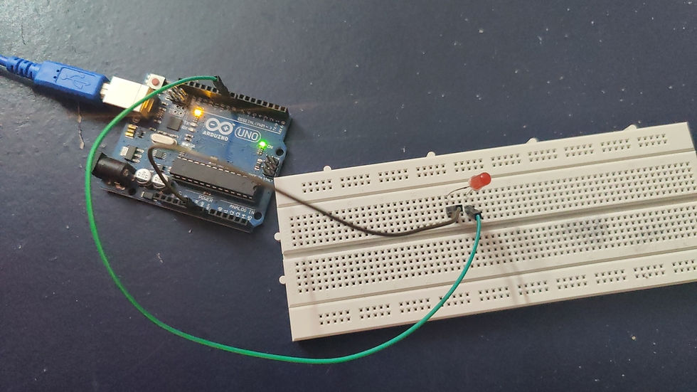
Circuit Connections
The connection for this circuit is simple. The positive terminal of the LED is connected to the PIN 9 of the Arduino UNO board. The red Jumper wire shows the same. The negative terminal of the LED is connected to the Ground(GND) pin of the Arduino UNO board. The second connection is shown by the Black Jumper wire.
The Arduino #UNO board is then connected to the system which has the IDE and the code is written for the circuit to work.
Code
Working
The working of the circuit is easy to understand.

When the connections are done and the system is connected to the circuit, the LED is initially OFF as it is initialized with '0' brightness. The LED is set to Output mode. The positive terminal of the LED receives Supply (voltage) from the Arduino board and starts working.
As per the delay given, after every particular amount of time, the LED continuously Fades IN and Fades out. As explained in the code, the LED brightness reaches the maximum value of 255 and is returned to the initial value. It again Fades IN in increments of 5 points and Fades OUT in the same way.
Check the Project Working video here - How to make an LED Fade in and out using Arduino | IoT LED project | LED Fade In and Fade Out |
Project video By - Abhishek Goud
This device is implemented on larger scales with more independence. It means that the controlling of the LED brightness need not be the same for all conditions. The involvement of IoT and #AI has increased its application in various fields. Try giving different conditions, attach sensors to take input values, and control the LED brightness depending upon the same. Start Exploring!!
SEE ALSO:
Click on the button below to fill out the project inquiry form -
Create Various Projects
Check out our Free Arduino Projects Playlist - Arduino Projects
Check out our Free Raspberry Pi Projects Playlist - Raspberry Pi Projects
Check out our Free TinkerCAD Projects Playlist - TinkerCAD Projects
Check out our Free IoT Projects Playlist - IoT Projects
Check out our Free Home Automation Projects Playlist - Home Automation Projects
Check out our Free NodeMCu Projects Playlist - NodeMCu Projects
What an excellent and informative guide! Learn Electronics India has nailed it with this blog on Fading LED using Arduino UNO. The step-by-step instructions were easy to follow, making it perfect for beginners like me. I can't wait to try this out and explore more Arduino projects
LearnElectronics India simplifies complex concepts beautifully. Thank you!