IoT - Distance measurement using Ultrasonic Sensor & Raspberry Pi
- Pooja Velavan

- Aug 22, 2020
- 6 min read
Updated: Sep 27, 2024
Internet of Things (IoT) refers to connecting all physical devices to the internet, to monitor and control it from any distant place. In this article, let us learn how to interface an Ultrasonic sensor with Raspberry pi for distance measurement.
An Ultrasonic Sensor is used to measures the distance of an object or obstacle via Ultrasonic waves (that travel faster than the speed of audible sound), and it converts the reflected ultrasonic waved into electric signals. It is commonly used in obstacle avoiding robots, blind Walking stick, and automation projects.
First, let us start with the requirements for the circuit connection.
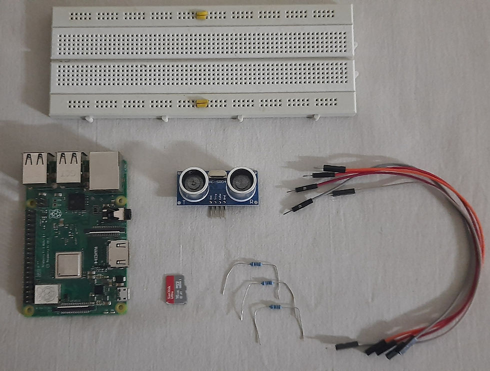
Hardware Requirements:
The image shows the list of components needed. Let's have a quick look at each of them.
1. HC-SR04 Ultrasonic Sensor

The HC-SR04 Ultrasonic Sensor is used for obstacle detection. An ultrasonic sensor contains two circular structures: one is the #transmitter and the other is a #receiver. The transmitter transmits the ultrasonic sound while the receiver receives the reflected signal. It consists of four pins. They are supply pin (Vcc), Trigger pin (Trig), Echo pin (Echo), and Ground pin (Gnd).
Buy an HC-SR04 Ultrasonic Sensor from here.
2. Raspberry pi
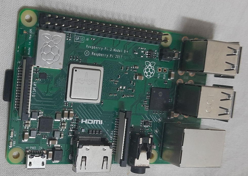
Unlike #Arduino, Raspberry Pi works with its own Operating System, Linux. So, Raspberry Pi can be called a single-board computer. It does not have any peripherals like a keyboard, mouse, etc. but works when connected to a system.
Features of Raspberry Pi:
SoC (System On Chip).
Integrated ARM-compatible central processing unit (CPU).
GPU (Graphics Processing Unit - on chip).
In this project, the Raspberry Pi Model B/B+ can be used, which have a 1.2GHz/1.4GHz processor. It has inbuilt WiFi and also Bluetooth capabilities.
Buy Raspberry Pi from here.
3. MicroSD Card

The MicroSD card used here needs to be loaded with Raspbian OS which is a zip file containing the code needed to run the #program on Raspberry Pi and allows interfacing between the hardware and software.
Buy a MicroSD Card from here.
4. 1K Ohm Resistors
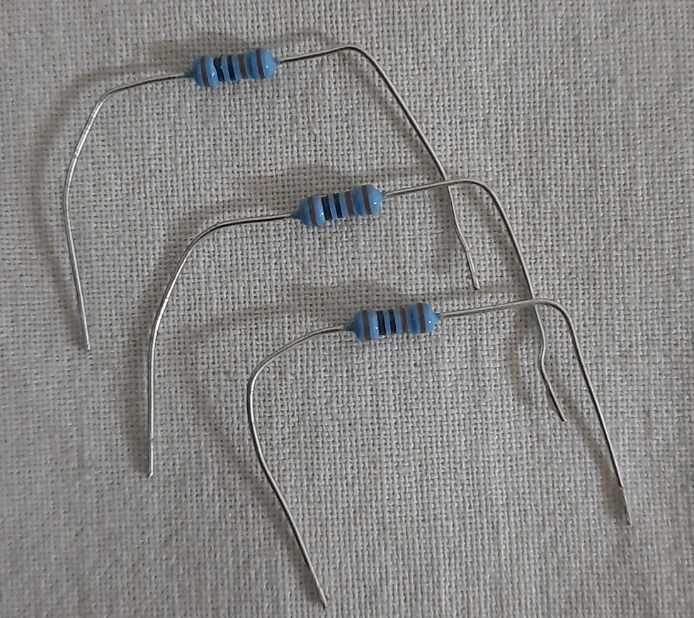
Resistors are passive devices that restrict the flow of current or divide the voltage through the circuit. The input power passes through these resistors and then to the sensors to avoid damage.
Buy Resistors from here.
5. Breadboard

A breadboard is a rectangular board with small holes in which elements are connected. The connections are not fixed and can be varied. In a breadboard, the holes in one horizontal line are in series connection with each other. Breadboards are made from plastic and come in all shapes, sizes, and even different colors, the most commonly used types are "full-size," "half-size," and "mini" breadboards.
Buy the Breadboard from here.
6. USB Cable

This cable is used to connect the RaspberryPi to the power supply. It also helps in the transmission of data.
Buy USB Cable from here.
7. Jumper Wires

Jumper wires are used to establish a connection between different elements in the circuit and the #Raspberrypi board. There are two types of wire, male and female. The male wires have ends that can be connected to other ends and the female wires are the ones that have the receiving end.
Buy Jumper Wires from here.
Software Requirements:
1. ThinkSpeak

ThinkSpeak cloud is an open-source IoT application that provides API to store and retrieve data from the data given through the device connected to it. It uses HTTP and MQTT protocols. ThinkSpeak is a cross-platform which is used for data analysis( by plotting real-time graphs) and has a grown relation with Map-labs. It also has a numerical computing software MatLab for map-works.
2. Raspberry pi Imager

The software is used to allow the interfacing of the hardware devices and software applications. This software needs to be downloaded into the system for the Raspberry Pi Chip to be recognizable.
3. Python IDLE IDE

The main software application is a #Python IDE for this device to work. The code is written in the notepad and saved with a .py extension so that it becomes a python code file and can be interfaced with the device.
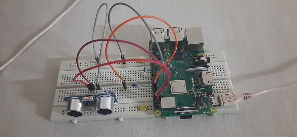
Circuit Connection:
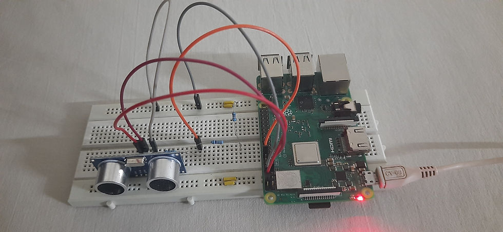
The Circuit connection for this project is shown. As stated above, the Ultrasonic sensor has four pins.
The supply pin (Vcc) is connected to the 5Volt pin of the Raspberry pi.
The Trigger pin (Trig) is used to generate the sound waves and the Trigger pin is connected to pin 7 in the raspberry pi board.
The Echo pin is used to receive the reflected sound waves based on the sound signal transmitted. The transmitted sound signal hits an object and bounces back from the object is received by the receiver. The time taken by the signal to reach the receiver after hitting the object is recorded, by which the distance is calculated between the object and sensor.
The Echo pins are connected to the 2 resistors - 1K ohm and 2K ohm resistors. 1K ohm is connected to the echo pin and on another side, 2K ohm is connected by using the breadboard. And another end of the 2K ohm is connected to the negative terminal of the breadboard.
The resistors are connected to prevent the damages caused while connecting to the pins of the raspberry pi.
Between the two resistors, a divider line is created by which the echo pin is connected to pin 16 of the raspberry pi.
The Ground pin of the sensor and the Raspberry pi is commonly connected to the negative terminal of the breadboard to make a common ground connection.
The Raspberry Pi board is then connected to the computer through the #USB cable where the software is interfaced with the hardware device.
Download the code from here
Working:
The following images show how the circuit looks when connected and assembled.
Once the circuit connections are completed and the code is written in the #IDE, connect the hardware device to the computer and interface the code to the hardware.

The code is written in a notepad file and saved as a python file which creates the type of document required for the code execution.

After the file with the code is saved under the given extension, the #SSH (Secure Socket Shell) Terminal is opened.

The saved file name is entered and is then opened in the terminal. The output of which is shown above in the image.
By the time the terminal with the file and code is opened, the Thinkspeak cloud application must be opened and an account is created. Create a new channel for the project and add widgets and configure the parameters. Here the field is chosen in Distance in centimeter-scale with Numeric display.
The below image displays the output implementation when the hand is kept has an obstruction in front of the sensor, the output display shows the distance of the object.

When there is no obstruction in front of the sensor the output is displayed as:

A further detailed explanation of the circuit building, coding part, and the working with the terminal is explained clearly in the video.
Check the Project Working video here - Object Distance Calculation using Raspberry Pi and Ultrasonic sensor | HC SR04 | IoT | ThingSpeak
Video By - Sai Parimal
#Interfacing Ultrasonic sensor for IoT #applications helps in creating basic automation projects. It is a basic project to be known for creating or applying it to design various project applications and in huge automation systems.
See also:
Order Electronics Projects
Want us to guide you through your project or make the project for you? Click on the button below or reach out to us via Call/WhatsApp at (+91) - 7600948607
You can -
Order Basic Electronics Projects
Order Embedded Systems Projects
Order IoT Projects
Order FPGA Projects
Order VLSI Projects
Order Image Processing Projects
Order Matlab Projects
Order TinkerCAD Projects
Order Proteus Projects
Click on the button below to fill out the project inquiry form -
Create Various Projects
Check out our Free Arduino Projects Playlist - Arduino Projects
Check out our Free Raspberry Pi Projects Playlist - Raspberry Pi Projects
Check out our Free TinkerCAD Projects Playlist - TinkerCAD Projects
Check out our Free IoT Projects Playlist - IoT Projects
Check out our Free Home Automation Projects Playlist - Home Automation Projects
Check out our Free NodeMCu Projects Playlist - NodeMCu Projects
Follow us -
Please do follow us i.e. #learnelectronicsindia to get daily updates about new blogs, videos, courses, products, offers, competitions, quizzes, and Internship Opportunities.
Learn Electronics India has outdone themselves with this outstanding piece on Ultrasonic Sensor and Raspberry Pi integration for distance measurement. The clear explanations and DIY approach make it enjoyable for beginners and hobbyists alike. Highly recommended.
Short and effective! LearnElectronics India never disappoints.