
Interfacing Tilt Ball Switch using Arduino
- Kiranmai Chigurupati

- May 28, 2021
- 3 min read
Updated: Sep 15, 2024
In this project, we use a tilt ball switch that powers the circuit based on its orientation. The tilt ball switch will have a freely moving metal ball inside the cylinder. Based on the position or orientation of the switch, the ball will turn ON the switch by coming into contact with the two terminals and vice versa.
Hardware requirements:
Arduino UNO:
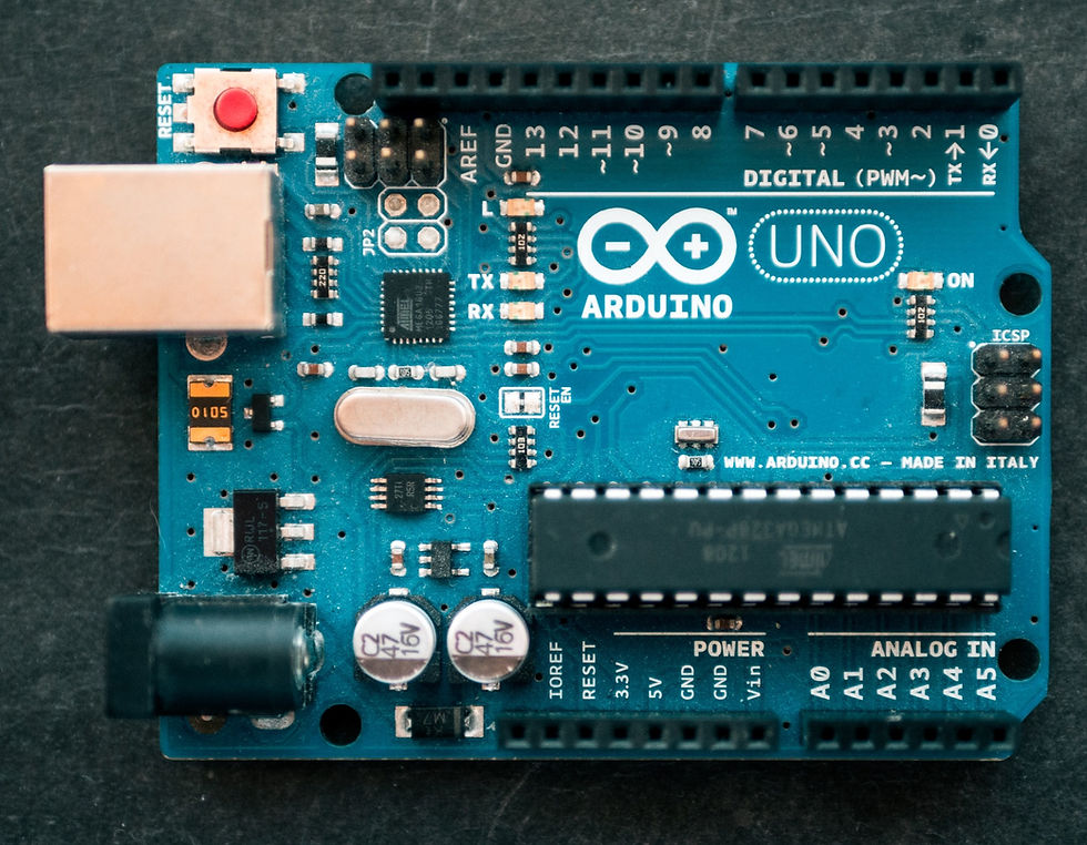
The Arduino is a programmable #microcontroller, it's an open-source electronics proto-type platform. It interacts with the user by receiving input with the aid of sensors and provides the output employing LED, buzzer, etc.,
In order to know more about the Arduino UNO, refer to this article.
Breadboard:

A #breadboard is a flat piece of wood that is provided with holes that allow users to build a circuit including the components and connections without the need for soldering due to which it is reusable and finds its best usage for the students who are new to build circuits. The holes in any horizontal line will be in series whereas the vertical holes remain at an equipotential state. There are different sizes of breadboards available in the market which include "full size", "half-size" and, "mini-size" breadboards.
LED:

LED is a semiconductor light source that emits light when a current passes through it. Electrons in the semiconductor combine with holes by passing through the gap which inturns release energy in the form of photons.
Resistor:

A resistor as the name signifies opposes the flow of electrons. The Resistor is a passive element and has two terminals. They are used to monitor the current flow and also as voltage dividers. The #resistor that we would use in this circuit is a 220-ohm resistor and the color code for this resistor is Red, Red, Brown & Gold.
Tilt ball switch:

This switch is turned ON & OFF based on the orientation of the switch.

The metal ball placed in the cylinder makes and breaks the contact thus turning the switch ON & OFF respectively.
Software requirements:
Arduino IDE:

The Arduino Integrated Development Environment (IDE) is a cross-platform application (for Windows, macOS, Linux) that is written in functions from C and C++. It is used to write and upload programs to Arduino compatible boards, but also, with the help of third-party cores, other vendor development boards.
Circuit connection:
Circuit connection involves the following steps:
The Anode of the LED is connected to PIN number 9 of the Arduino and the Cathode of the LED is connected to the ground via a 220-ohm resistor.
One terminal of the tilt sensor is connected to PIN number 8 and its other terminal is connected to the ground of the Arduino.
Code
Working:
Project By - Anupama Koley and Neha Patil
See Also -


Content Written by-
Name - Kiranmai Chigurupati
Portfolio Link - click here
Order Electronics Projects
Want us to guide you through your project or make the project for you? Click on the button below or reach out to us via Call/WhatsApp at (+91) - 7600948607
You can -
Order Basic Electronics Projects
Order Embedded Systems Projects
Order IoT Projects
Order FPGA Projects
Order VLSI Projects
Order Image Processing Projects
Order Matlab Projects
Order TinkerCAD Projects
Order Proteus Projects
Click on the button below to fill out the project inquiry form -
Create Various Projects
Check out our Free Arduino Projects Playlist - Arduino Projects
Check out our Free Raspberry Pi Projects Playlist - Raspberry Pi Projects
Check out our Free TinkerCAD Projects Playlist - TinkerCAD Projects
Check out our Free IoT Projects Playlist - IoT Projects
Check out our Free Home Automation Projects Playlist - Home Automation Projects
Check out our Free NodeMCu Projects Playlist - NodeMCu Projects
Follow us -
Please do follow us i.e. #learnelectronicsindia to get daily updates about new blogs, videos, courses, products, offers, competitions, quizzes, and Internship Opportunities.
Informative and concise! LearnElectronics India always delivers quality content.
This blog deserves a round of applause! The author has managed to simplify a complex topic like interfacing tilt ball switches using Arduino, making it accessible even to beginners. Learn Electronics India's commitment to promoting electronics education is commendable, and I'm eagerly looking forward to more insightful articles like this one.