Making a calculator using Arduino and 4*4 Keypad
- Kiranmai Chigurupati

- May 8, 2021
- 3 min read
Updated: Jan 16, 2025
We use calculators more often in our daily life to perform many kinds of calculations for various purposes. In this blog, we will learn to make a calculator by interfacing a 4x4 keypad that takes input from the user and performs the arithmetic operations like addition, subtraction, multiplication, division and the result of the operation (i.e., output) will be displayed on the LCD screen.
Hardware Requirements:
1. 4x4 keypad:

A 4x4 matrix keypad is used as an input device that takes inputs from the users. It consists of 16 pins in total with four rows and four columns. On pressing a key, a connection will be established between the corresponding row and column between which the switch is placed.
2. Arduino UNO:

The Arduino is a programmable microcontroller, it's an open-source electronics proto-type platform. It interacts with the user by receiving input with the aid of sensors and provides the output employing LED, buzzer, etc.,
In order to know more about the Arduino UNO, refer to this article.
3. 16x2 LCD:
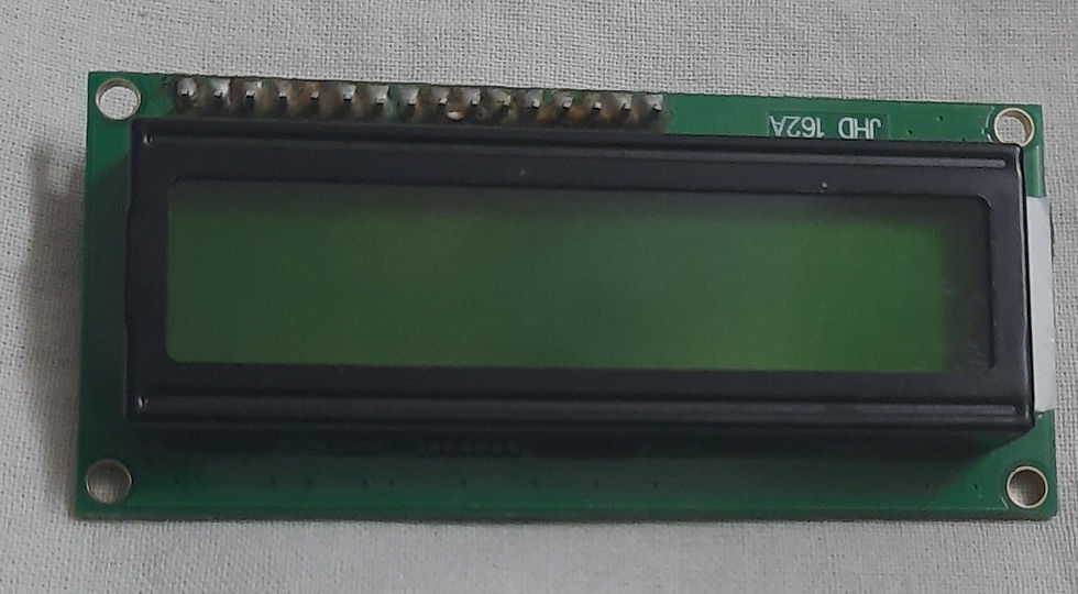
LCD- Liquid Crystal Display is an electronic module that uses liquid crystal to produce a visible image. It is the basic module that is generally used in DIY and circuits. The display segments are affordable and simply programmable.
4. Jumper Wires:

Jumper wires are used to establish connections between different components in the circuit.
Circuit Connection and its Working:
What goes where??
Circuit Connection involves the following steps:
Column pins C4-C1 of the keypad are connected to 6-9 PWM pins of the Arduino respectively.
Row pins R1-R4 of the keypad are connected to 10-13 PWM pins of the Arduino respectively.
The Ground pin of the LCD is connected to the GND pin of the Arduino.
Vcc of the LCD is connected to the 5V of the Arduino.
SDA is connected to analog pin 4 of the Arduino.
SCL is connected to analog pin 5 of the Arduino.
Code
Check the Project working video here - Interfacing 4x4 Keypad with Arduino | Making a calculator using Arduino | Arduino Calculator
Video by - Aishwarya Balajee and edited by Neha Patil
See also:
Order Electronics Projects
Want us to guide you through your project or make the project for you? Click on the button below or reach out to us via Call/WhatsApp at (+91) - 7600948607
You can -
Order Basic Electronics Projects
Order Embedded Systems Projects
Order IoT Projects
Order FPGA Projects
Order VLSI Projects
Order Image Processing Projects
Order Matlab Projects
Order TinkerCAD Projects
Order Proteus Projects
Click on the button below to fill out the project inquiry form -
Create Various Projects
Check out our Free Arduino Projects Playlist - Arduino Projects
Check out our Free Raspberry Pi Projects Playlist - Raspberry Pi Projects
Check out our Free TinkerCAD Projects Playlist - TinkerCAD Projects
Check out our Free IoT Projects Playlist - IoT Projects
Check out our Free Home Automation Projects Playlist - Home Automation Projects
Check out our Free NodeMCu Projects Playlist - NodeMCu Projects
Follow us -
Please do follow us i.e. #learnelectronicsindia to get daily updates about new blogs, videos, courses, products, offers, competitions, quizzes, and Internship Opportunities.
LearnElectronics India's explanation is spot-on. Great work!
Absolutely fantastic! I stumbled upon this blog by Learn Electronics India while searching for Arduino projects, and I must say, it exceeded my expectations. The calculator project with the 4x4 keypad is both practical and fun. I particularly appreciated the troubleshooting tips and suggestions for further customization. This blog is a goldmine for electronics enthusiasts and hobbyists. Thank you for sharing your expertise with us.