Interfacing the Arduino with an 8 multiply 8 LED Matrix
- Pooja Velavan

- Jan 15, 2021
- 4 min read
Updated: Sep 21, 2024
#LED lights are often used to display the output of any circuits. They are also packed into rows and columns of the matrix with a number of LED's has pixel to display the specific signs, symbols, or messages. These matrix arrangements are available in a combination of a single color or multi-color LEDs.
In this article, let us learn how to interface 8*8 LED matrix display with the #Arduino board and the coding to display the desired character in it. Let's quickly start with the requirements to build the project.
Hardware Requirements:
1. Breadboard

A breadboard is an essential component that is in a rectangular shape with small holes in it that are used to insert the components to test the circuits. The connections are not fixed and can be varied. In a breadboard, the holes in one horizontal line are in series connection with each other. Breadboards are made from plastic or wood and come in all shapes, sizes, and even different colors, the most commonly used sizes for designing the circuits are "full-size," "half-size," and "mini" breadboards.
Buy the Breadboard from here.
2. Arduino UNO
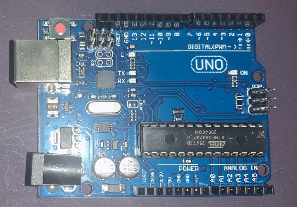
#Arduino board is a microcontroller that is used to accept inputs from sensors connected and provide an output action on the desired device connected to it. The sensor inputs can be from light-detecting sensors, motion sensors (Ultrasonic or IR), temperature sensors, etc. The output from this device can be received through other output devices such as LED, Buzzer, Serial monitor, etc.
Buy Arduino UNO from here.
3. 8*8 LED Matrix

8*8 LED #matrix consists of 64 pixels in which each pixel has a LED connected to it. The LED's are arranged in rows and columns in a matrix and are connected to the 16 pinouts.
Buy 8*8 LED Matrix from here.
4. Jumper Wires

These are the main components that are used to establish the connections between different devices of the circuit.
Buy Jumper Wires from here.
5. USB Cable

This cable is used to connect the Arduino board to the power supply. It also helps in the transmission of data.
Buy USB Cable from here.
Software Requirements:
1. Arduino IDE

Arduino #IDE (Integrated Development Platform) which is used to interface the Development boards like NodeMCU to run the desired code designed to #interface hardware devices.
Circuit Connections and its Working:
The Circuit connection between the #LED Matrix and Arduino involves the following steps.
First, we have to determine which is the Row pins and Column pins out of the 16 pins. There are 8 rows and 8 columns in the matrix.
On determining the rows and columns, connect the pins accordingly to the Arduino board.
Based on the LED positioning the connection can be done by connecting the row pin to the supply voltage of the Arduino board and the column pin to the ground.
Hence, there are 16 pins in the matrix the connection is a little bit complicated. Let us see which pin is to be connected to which row and column:
ROW_1 to DIGITAL PIN 2
ROW_2 to DIGITAL PIN 3
ROW_3 to DIGITAL PIN 4
ROW_4 to DIGITAL PIN 5
ROW_5 to DIGITAL PIN 6
ROW_6 to DIGITAL PIN 7
ROW_7 to DIGITAL PIN 8
ROW_8 to DIGITAL PIN 9
COLUMN_1 to DIGITAL PIN 10
COLUMN_2 to DIGITAL PIN 11
COLUMN_3 to DIGITAL PIN 12
COLUMN_4 to DIGITAL PIN 13
COLUMN_5 to ANALOG PIN A0
COLUMN_6 to ANALOG PIN A1
COLUMN_7 to ANALOG PIN A2
COLUMN_8 to ANALOG PIN A3
Code
Note: Please change the file extension to .ino(Arduino IDE) file format before you upload the code to the Arduino board.
Check the Project working video here - Interfacing the Arduino with an 8x8 LED Matrix
Video By - Aishwarya Balajee
The LED matrix finds its application in Traffic Lights, Text signs, or emojis, Signboards, etc. Take the first step to design the circuit by keeping this article as a basic tutorial and try to develop the circuit on your own. Try yourself by creating patterns or symbols in the LED matrix by making the respective LEDs to glow and create or modify the coding part according to your desired output.
See also:
Order Electronics Projects
Want us to guide you through your project or make the project for you? Click on the button below or reach out to us via Call/WhatsApp at (+91) - 7600948607
You can -
Order Basic Electronics Projects
Order Embedded Systems Projects
Order IoT Projects
Order FPGA Projects
Order VLSI Projects
Order Image Processing Projects
Order Matlab Projects
Order TinkerCAD Projects
Order Proteus Projects
Click on the button below to fill out the project inquiry form -
Create Various Projects
Check out our Free Arduino Projects Playlist - Arduino Projects
Check out our Free Raspberry Pi Projects Playlist - Raspberry Pi Projects
Check out our Free TinkerCAD Projects Playlist - TinkerCAD Projects
Check out our Free IoT Projects Playlist - IoT Projects
Check out our Free Home Automation Projects Playlist - Home Automation Projects
Check out our Free NodeMCu Projects Playlist - NodeMCu Projects
Follow us -
Please do follow us i.e. #learnelectronicsindia to get daily updates about new blogs, videos, courses, products, offers, competitions, quizzes, and Internship Opportunities.
Informative and concise! LearnElectronics India always delivers quality content.
This blog post deserves a standing ovation! I've always wanted to work with LED matrices, and thanks to Learn Electronics India, I can now confidently dive into more complex projects. I'm genuinely grateful.