Adders and Subtractors
- Usha Saha

- Sep 19, 2020
- 4 min read
Updated: Sep 25, 2024
Modern-day is the era of digital electronics, digital systems, and moreover the digital world. What do these digital systems comprise of, how do they operate and many similar questions are there? Today let's answer some of these questions with the help of some digital circuit elements. Through this article, we would cover the two crucial #arithmetic circuits, those are #adders and subtractors.
Adders and #subtractor come under the category of combinational circuits. Combinational Logic Circuits as the name suggest consisting of a combination of logic gates whose output at any instant of time is calculated by the present combination of inputs only. Combinational circuits, therefore, are also called a memoryless system as the output is only dependent on the present values of input.
Adders
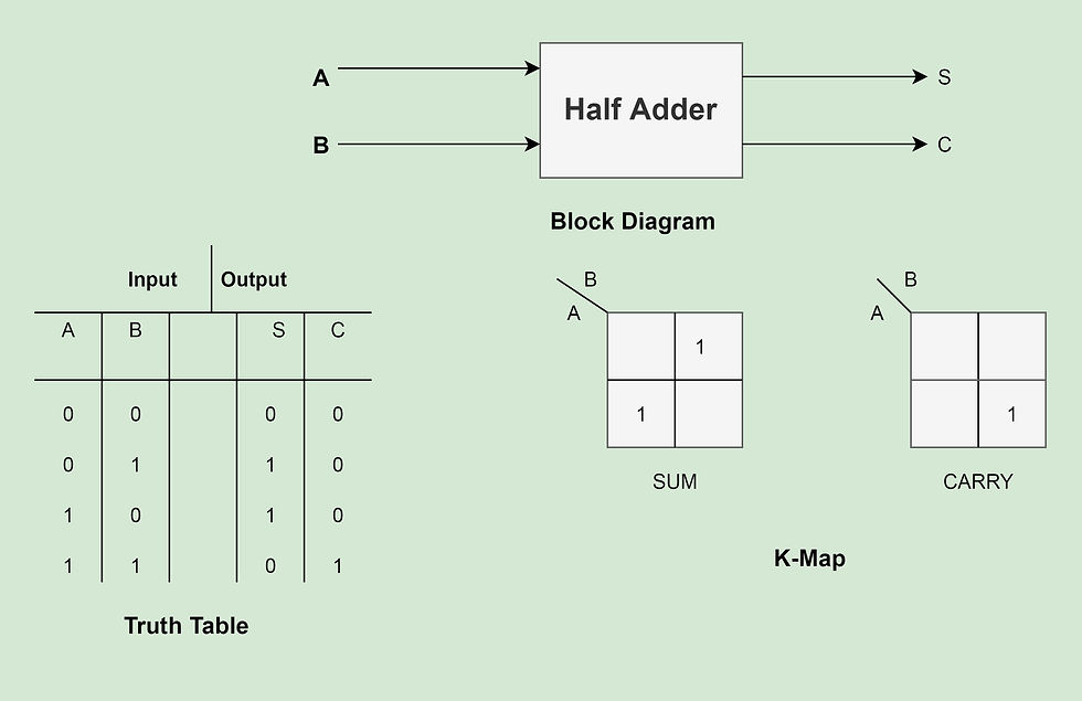
The Half-Adder:- The half adder is an arithmetic circuit used to perform two single-bit addition. The input to the half adder is a two-bit data while the output comprises sum and carry outputs. For better understanding purposes let us have a look at the block diagram of a half adder circuit where A and B be the two inputs, and S(sum) and C(carry) are the two outputs.
Sum=A'B+AB' (From the K-Map).
Carry=AB (From the K-Map).
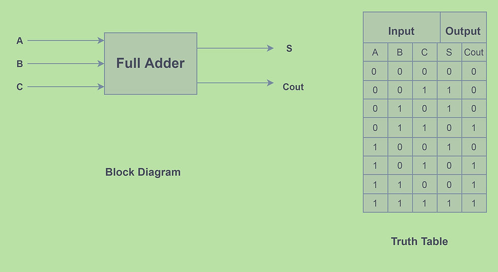
Full Adder:- Similiar to half adder a full adder is also an #arithmetic circuit, used to perform the addition of three input bits. There are three input lines (assume A, B and, C) and two output lines namely sum and carry/Cout. Let us take a look at the block diagram, truth table, and k-map of a full adder for a better concept.
Substituting the sum and carry value in the K-map for simplification purpose, we get the K-map as below.
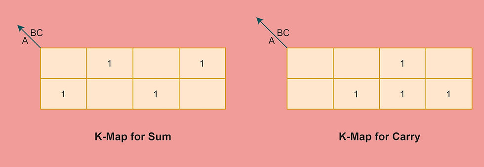
By solving the K-map
Sum= A'B'C+A'BC'+AB'C'+ABC
Carry= AB+BC+CA
The sum and carry can also be written in terms of minterms
Sum= Summation(1,2,4,7)
Carry=Summation(3,5,6,7)
Binary Parallel adder:- Another type of adder is a binary adder that adds two binary numbers in parallel form. It constitutes full adders connected in cascade, where the output carry from each full adder is connected to the input carry of the next adder.
Hence 'n' binary parallel adder can be implemented by:-
n full adders.
(n-1) full adder and a half adder
(n-1)[2 half adder + 1 OR gate] and a half adder.
(2n-1) half adder and (n-1) OR gates.
Key point:- In 'n' bit parallel adder minimum delay to produce the final output is 2nt(pd).
here t(pd) is the propagation delay of each adder. This propagation delay makes the parallel adder very slow, to overcome this another adder is used known as The look-ahead carry adder.
Look-ahead carry adder:- A look ahead eliminates the propagation delay of the binary adder and speeds up the process. It examines all the input bits simultaneously and also generates the carry bit for all the stages simultaneously.
Additional information
A half adder can be implemented using universal gates, that is by NAND or NOR gates. A total of 5 NAND/NOR gate is required to implement a half adder.
A full adder can be implemented using universal gates, that is by NAND or NOR gates. A total of 9 NAND/NOR gate is required to implement a full adder.
Subtractors
A half-subtractor:- A half subtractor is another #combinational circuit that performs one-bit subtraction to generate a difference. The block diagram of a half subtractor is shown below. There are two input lines namely A and B, and two output lines namely difference(d) and borrow(b).
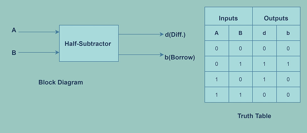
By solving the outputs of half subtractor using K-map the difference and borrow are as follows.
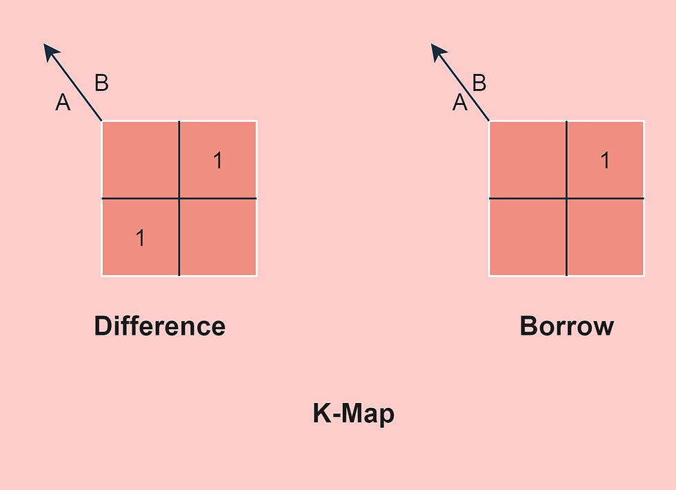
Difference= A'B+AB'
Borrow= A'B
The Full subtractor:- The full subtractor as the name signifies performs the arithmetic subtraction of the three input data line and gives an output. The block diagram of a full subtractor is as below. It comprises three input lines A, B, and, C and two output lines d (difference) and b (borrow).
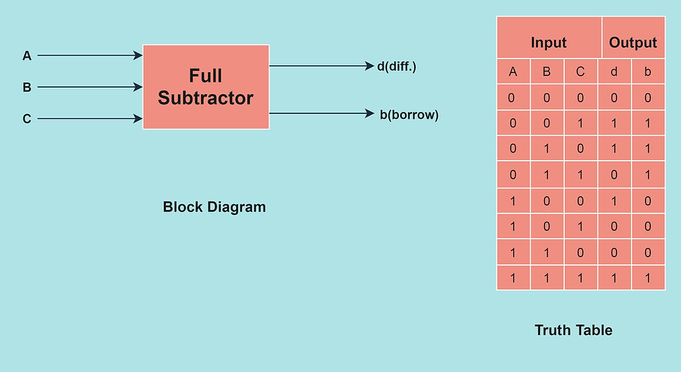
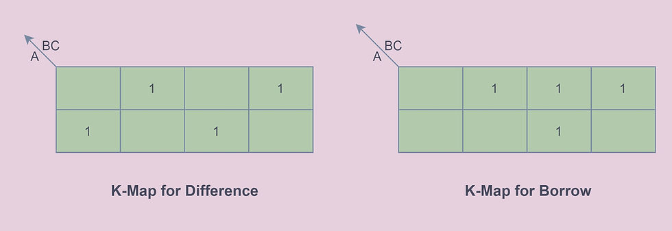
The difference and borrow as determined by the truth table and the k-map is as follows.
Difference= A'B'C+A'BC'+AB'C'+ABC
Borrow=A'C+A'B+BC
Key points
A half subtractor can be implemented using universal gates, that is by NAND or NOR gates. A total of 5 NAND/NOR gate is required to implement a half subtractor.
A full subtractor can be implemented using universal gates, that is by NAND or NOR gates. A total of 9 NAND/NOR gate is required to implement a full subtractor.
A minimum of 2x1 MUX is required to implement a half adder/half subtractor.
Half Adder+Inverter=Half subtractor
Full Adder=2 Half Adder+ OR gate.
Full Subtractor=2 Half Subtractor+ OR gate.
See Also
Order Electronics Projects
Want us to guide you through your project or make the project for you? Click on the button below or reach out to us via Call/WhatsApp at (+91) - 7600948607
You can -
Order Basic Electronics Projects
Order Embedded Systems Projects
Order IoT Projects
Order FPGA Projects
Order VLSI Projects
Order Image Processing Projects
Order Matlab Projects
Order TinkerCAD Projects
Order Proteus Projects
Click on the button below to fill out the project inquiry form -
Create Various Projects
Check out our Free Arduino Projects Playlist - Arduino Projects
Check out our Free Raspberry Pi Projects Playlist - Raspberry Pi Projects
Check out our Free TinkerCAD Projects Playlist - TinkerCAD Projects
Check out our Free IoT Projects Playlist - IoT Projects
Check out our Free Home Automation Projects Playlist - Home Automation Projects
Check out our Free NodeMCu Projects Playlist - NodeMCu Projects
Follow us -
Please do follow us i.e. #learnelectronicsindia to get daily updates about new blogs, videos, courses, products, offers, competitions, quizzes, and Internship Opportunities.
A big shoutout to the author for this outstanding blog! The step-by-step breakdown of adders and subtractors really helped me grasp the underlying principles. I'll definitely be coming back to this site for more electronics-related content.
Brilliant explanation! Thanks, LearnElectronics India!