Smart Lighting System - IoT Prototype using Blynk App
- LearnElectronics India

- Jul 8, 2020
- 5 min read
Updated: Sep 29, 2024
The most standard entry into the world of automation is with a smart lighting system. Are the "Internet of Things" and Home Automation just lingos? In this project check out how we can bring home automation onto our finger-tips in our daily routine to make life much easier!
Here we use the Blynk app which is a mobile application designed to control electrical appliances. The article provides step by step instructions involved in this interfacing which is pretty simple, starting from the list of electronic components required.
Apparatus Required:
The list provides all the hardware and software components required for the interfacing are as follows.
Hardware components:
1.LDR Sensor:
This is a cadmium-sulfide cell works based on the principle of Photoconductivity. It is basically a resistor whose resistance value changes depending upon the intensity of light. When the light falls on the surface of the senor, material conductivity varies as a result of which resistance also varies.

Buy the LDR Sensor module from here.
2. Raspberry Pi 3:
We are using #Raspberrypi to connect with the LEDs, the #LDR sensor, and display the output. It contains several I/O pins using which we can connect the module and then by coding the Raspberrypi, we will receive the commands/signals that are sent from the mobile. This powerful credit-card-sized single-board computer can be used for many applications and supersedes the original Raspberry Pi Model.
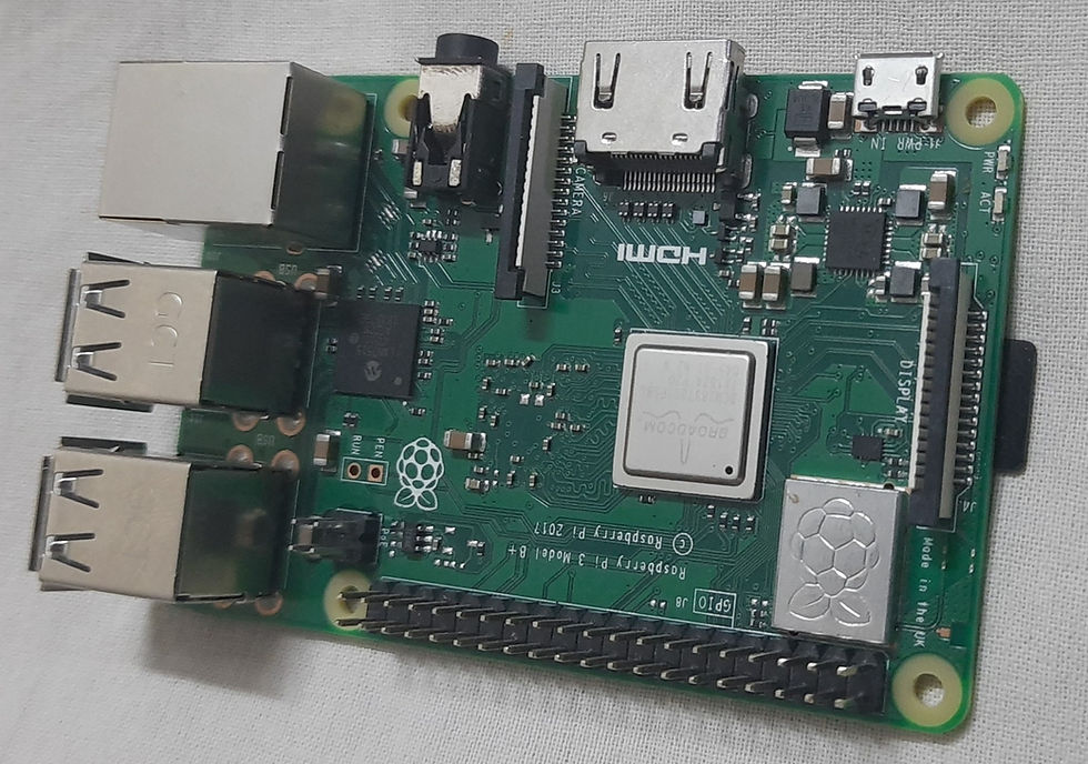
Buy Raspberry Pi 3B+ from here.
3. Jumper wires:
These are simple connecting electrical wires, that are used to connect the ends without any soldering. The male wires have ends that can be connected to other ends and the female wires are the ones that have the receiving end. Grouping these wires a cable can be formed.

Buy Jumper wires from here.
4. USB Cable:
This USB cable is used to connect the Raspberry Pi to the power supply. It also helps in the transmission of data.

Buy USB Cable from here.
5. Capacitor:
The resistance measured by the LDR sensor is done with the help of the time constant concept. The time required to charge a capacitor is equal to the multiplied value of resistance of the circuit and capacitance. Here, a 0.1 uF capacitor is used.

Buy Ceramic Capacitor from here.
The link is missing.
6.Bread Board:
The breadboard is the basic component of any circuit building process. All components, be it input sensors or output display devices are connected to the Raspberry Pi or any other microcontroller using wired connections through a breadboard. The holes in the breadboard are in series. There are various sizes like full-sized, half-sized, and mini breadboards.

Buy Breadboard from here.
Software components:
7.SSH Terminal:
The SHH Terminal is used in this project to connect the Raspberry Pi module to the terminal of another computer or peripheral device. Encrypted data transfer between two computers is supported by this terminal.

8.Python IDE:
Programming is done in #Python language in an IDE (Integrated Development Environment) which is a platform where we can not only write the code but also run, and test the working.

CIRCUIT DIAGRAM:
In this section, let's see all the connections of the circuit with all the components whose brief introduction is given above.
What goes where?
The Blue line connects one terminal of the #LDRsensor to GPIO 17 pin, of the Raspberry Pi module, that is the board pin number 11. The other end of the sensor is connected to one end of the capacitor.
The orange line connects this end to the GPIO 27 pin of the Raspberry Pi 3, which is the board pin number 13.
Another end of the capacitor is connected by the Black wire to the ground (GND) pin of the Pi module.
NOTE: Basically these pin numberings are useful for writing python scripts for the Raspberry Pi.
Now the LEDs which are an alternative for the lights and bulbs at our home, here we see that the GPIO pins, the board pin number 18, 15, and 16 of the Raspberry Pi are connected to the LEDs here in the circuit. The GPOIs connected with the resistors, the resistors in turn connected with the anode of the LED, and the cathode connected to the ground(GND).
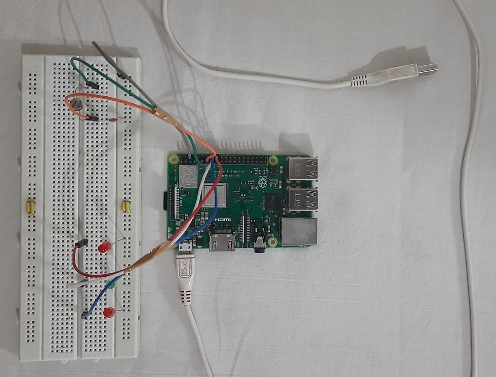
The above image depicts the hardware circuit when unpowered, before any code implementation.

Here, the above image depicts the hardware circuit when it is powered up, the setup is ready for the program to run using the raspberry Pi terminal.
Download the complete code here.
Working:
We have to configure our Blynk app with respective buttons to show the output. Create a new project and select the device Raspberry Pi 3. Enter the value display settings and allocate virtual buttons for each LED. The virtual buttons are used to display the data on the app.
The V5 button is for LED 1.
The V7 button is for LED 2.
The V6 button is for LED 3.
V8 button is to select either smart mode or the manual mode.
In Smart mode, the LEDs get ON once the resistance value is above the default threshold value. Here, the threshold value is 500 ohm. In manual mode, irrespective of the threshold value the ON/OFF of the LEDs is determined manually.
After the execution of the code, now let us check the working of the circuit. Now the setup is in manual mode.
MANUAL MODE:
When the virtual button for LED 1 is ON, the corresponding output is:

When the virtual button for LED 2 is ON, the output is:

Similarly, when the virtual button for LED 3 is ON, the output is:

When all the three virtual buttons are ON, the output is:

When all the three virtual buttons are OFF, the output is:

We can also perform operations such as all buttons are OFF, only 2 buttons in ON state, and obtain the respective output.
SMART MODE:
Now the setup is switched to the smart mode. At first, all three LEDs are glowing because the LDR value is above the threshold value (500 ohms).

When the mobile flashlight is on, the LDR value starts decreasing. At some point, it gets below the default threshold value and all the LEDs get OFF.

Check the Project working video here - Smart Lighting System - IoT Project using Blynk App
Video By - Sai Parimal
For most of us controlling lights was all about flipping lots of switches, but now we know how smart automated lighting revolutionizes the way we experience lighting. This article lay as the basement for the construction of greater ideas. So, you can use this wide range of automation ideas or create ideas of your own. What are you waiting for? Let's get started.
For all the lines marked with red Reframe them. And do not remove the marks.
See also:
Order Electronics Projects
Want us to guide you through your project or make the project for you? Click on the button below or reach out to us via Call/WhatsApp at (+91) - 7600948607
You can -
Order Basic Electronics Projects
Order Embedded Systems Projects
Order IoT Projects
Order FPGA Projects
Order VLSI Projects
Order Image Processing Projects
Order Matlab Projects
Order TinkerCAD Projects
Order Proteus Projects
Click on the button below to fill out the project inquiry form -
Create Various Projects
Check out our Free Arduino Projects Playlist - Arduino Projects
Check out our Free Raspberry Pi Projects Playlist - Raspberry Pi Projects
Check out our Free TinkerCAD Projects Playlist - TinkerCAD Projects
Check out our Free IoT Projects Playlist - IoT Projects
Check out our Free Home Automation Projects Playlist - Home Automation Projects
Check out our Free NodeMCu Projects Playlist - NodeMCu Projects
Follow us -
Please do follow us i.e. #learnelectronicsindia to get daily updates about new blogs, videos, courses, products, offers, competitions, quizzes, and Internship Opportunities.
This blog/article is a fantastic resource for both beginners and enthusiasts in the IoT domain. The Smart Lighting System using Blynk App tutorial by Learn Electronics India is comprehensive, well-illustrated, and deserves all the praise.
LearnElectronics India simplifies complex concepts beautifully. Thank you!