


IR Remote Controlled LED Toggle System Using Arduino UNO
Introduction
Infrared (IR) communication is one of the simplest and most widely used wireless communication technologies for short-range electronic control. It is commonly found in televisions, air conditioners, music systems, and many other household appliances, where an IR remote allows users to send commands without any physical connection. Every button on an IR remote transmits a unique infrared signal that can be detected and interpreted by an IR receiver.
Arduino UNO provides an excellent platform for developing interactive embedded system projects due to its simple programming environment, large community support, and compatibility with numerous electronic modules. By interfacing an IR receiver module with the Arduino, it becomes possible to receive commands from an IR remote and perform different actions based on the button pressed.
In this project, an Arduino UNO is used to control ten LEDs using a standard IR remote control. Each numeric button (0–9) on the remote is assigned to a dedicated LED. Whenever a button is pressed, the Arduino receives the corresponding IR command, decodes it using the IRremote library, and compares it with predefined commands in the program. If a matching command is found, the corresponding LED changes its current state—turning ON if it was OFF, or turning OFF if it was already ON. At the same time, the received hexadecimal IR command and the LED status are displayed on the Serial Monitor for monitoring and debugging purposes.
Besides demonstrating digital output control, this project introduces fundamental concepts of infrared communication, signal decoding, decision making using switch-case statements, state management using arrays, and embedded programming with Arduino. It serves as an excellent beginner-friendly project while also providing a solid foundation for more advanced home automation and remote-controlled embedded applications.
What You'll Learn
By following this project, you will learn:
How infrared (IR) communication works between a remote control and an IR receiver.
How to interface an IR receiver module with an Arduino UNO.
How the IRremote library is used to decode IR signals.
How unique hexadecimal IR commands are used to identify different remote buttons.
How to control multiple LEDs using digital output pins.
How to implement LED toggling using programming logic.
How to use arrays to store the current state of LEDs.
How to display debugging information using the Arduino Serial Monitor.
Components Required
The following components are required to build the IR Remote Controlled LED Toggle System using Arduino UNO:
Component | Quantity | Purpose |
Arduino UNO | 1 | Main microcontroller used to process IR signals and control LEDs |
IR Receiver Module | 1 | Receives infrared signals transmitted by the remote control |
IR Remote Control | 1 | Sends unique IR commands to control the LEDs |
LEDs | 10 | Used to visually indicate the ON/OFF status |
220 Ω Resistors | 10 | Protect LEDs by limiting the current |
Breadboard | 1 | Provides a solderless platform for assembling the circuit |
Jumper Wires | As required | Used for electrical connections |
USB Cable | 1 | Powers the Arduino and uploads the program |
Project Overview
Before building the circuit and understanding the program, it is helpful to understand the overall operation of the system.
The user presses a numeric button (0–9) on the IR remote control.
The remote transmits a unique infrared (IR) command corresponding to the pressed button.
The IR receiver module detects the infrared signal and sends it to the Arduino UNO.
The Arduino decodes the received IR command using the IRremote library.
The decoded command is compared with the predefined hexadecimal values stored in the program.
If a matching command is found, the corresponding LED changes its state (ON to OFF or OFF to ON).
The received hexadecimal command and the current LED status are displayed on the Serial Monitor for debugging and verification.
Circuit Diagram
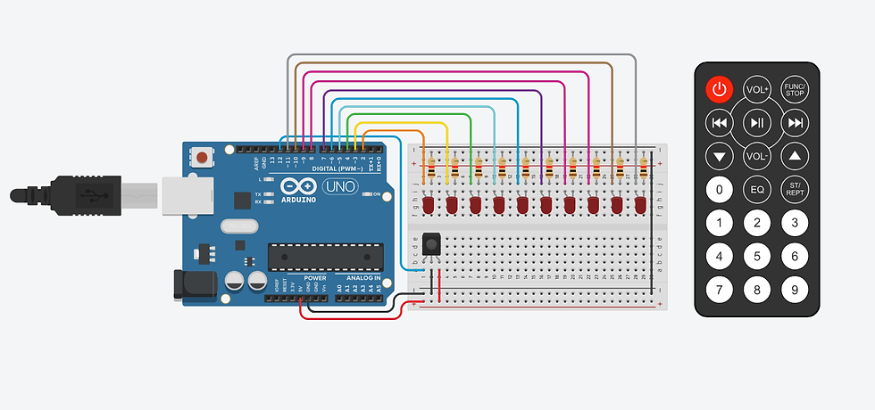
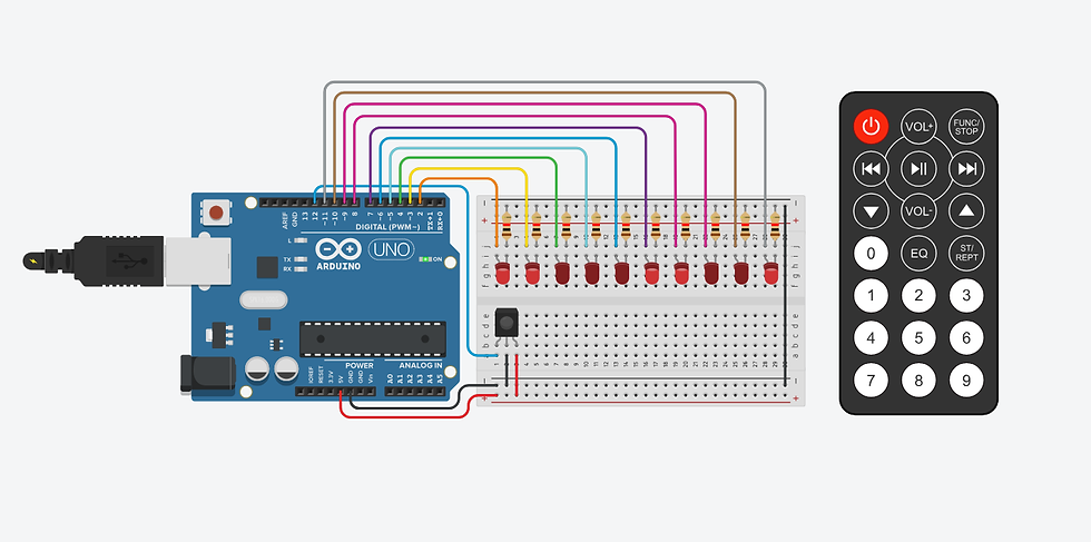
The circuit for this project was designed and simulated using Tinkercad, an online electronics simulation platform. The Arduino UNO acts as the main controller, receiving infrared signals from the IR receiver module and controlling ten LEDs based on the received commands. Each LED is connected to an individual digital output pin through a current-limiting resistor to ensure safe operation.
Circuit Connections
The following connections are used to interface the Arduino UNO, IR receiver module, and LEDs:
IR Receiver Connections
OUT → Arduino Digital Pin 12
VCC → Arduino 5V
GND → Arduino GND
LED Connections
LED 0 → Digital Pin 2
LED 1 → Digital Pin 3
LED 2 → Digital Pin 4
LED 3 → Digital Pin 5
LED 4 → Digital Pin 6
LED 5 → Digital Pin 7
LED 6 → Digital Pin 8
LED 7 → Digital Pin 9
LED 8 → Digital Pin 10
LED 9 → Digital Pin 11
Each LED is connected in series with a 220 Ω resistor to limit the current and protect the LED from excessive current flow.
The Arduino is powered through the USB connection, while the breadboard distributes the required 5V and GND connections to the IR receiver and other components.
Working Principle
The project works by establishing communication between an IR remote control, an IR receiver module, and an Arduino UNO. When a numeric button (0–9) on the IR remote is pressed, the remote transmits a unique infrared (IR) signal. The IR receiver module detects this signal and sends it to the Arduino through digital pin 12.
Using the IRremote library, the Arduino decodes the received IR signal into a unique hexadecimal value. Each button on the remote is associated with a specific hexadecimal command, which is compared with predefined values in the program using a switch-case statement. When a matching command is found, the Arduino identifies which button was pressed and executes the corresponding action.
Each numeric button is assigned to one LED connected to Arduino digital pins 2 through 11. Instead of simply turning an LED ON, the program uses a toggle mechanism. This means that pressing the same button repeatedly alternates the LED between ON and OFF states.
To keep track of whether each LED is currently ON or OFF, the program stores the state of every LED in an integer array named voltage[]. This allows the Arduino to remember the previous state of each LED and toggle it correctly whenever the corresponding button is pressed.
For debugging purposes, the decoded hexadecimal IR command and the current LED status are displayed in the Serial Monitor. Depending on the remote and IR protocol, an additional value of 0 may appear after the actual hexadecimal command. This represents a repeat frame generated by the remote and is ignored by the project logic.
Source Code
You can download the complete Arduino source code for this project using the download option provided below.
Code Explanation
The program begins by including the IRremote library, which provides all the functions required to receive and decode infrared signals from the IR receiver module. The IR receiver is connected to Arduino digital pin 12.

The setup() function initializes serial communication, starts the IR receiver, and con
s all LED pins as output pins. Initially, all LEDs are turned OFF.
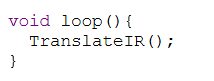
The loop() function continuously waits for an IR signal. Whenever a button is pressed, the received command is decoded and passed to the TranslateIR() function.
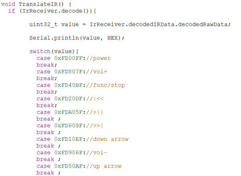
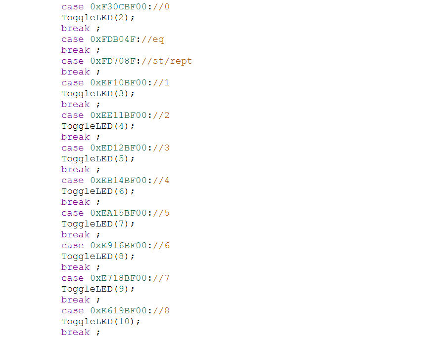

The TranslateIR() function compares the received hexadecimal command with predefined values using a switch-case statement. If a matching command is found, it calls the ToggleLED() function for the corresponding LED.
IrReceiver.resume() resets the IR receiver so it can receive and decode the next button press.
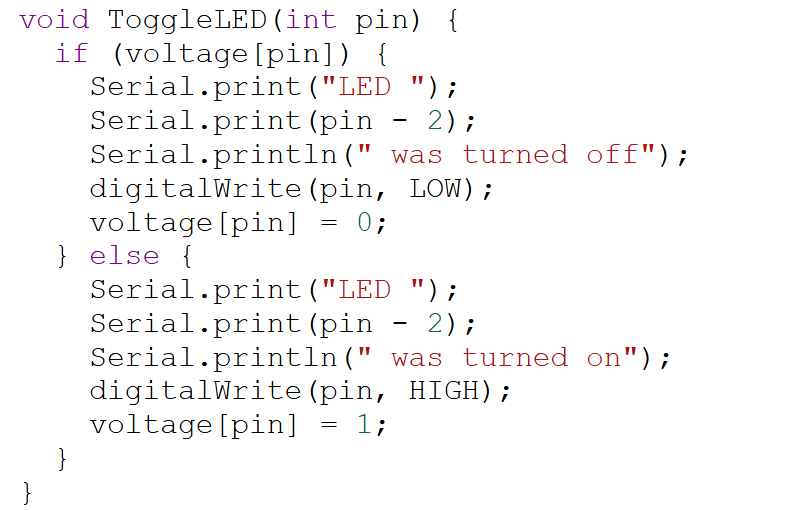
The ToggleLED() function checks the current state of the selected LED using the voltage[] array. If the LED is OFF, it turns it ON. If it is already ON, it turns it OFF. The updated LED status is also displayed in the Serial Monitor.
This modular programming approach improves code readability, makes debugging easier, and allows additional remote buttons or LEDs to be added with minimal code modifications.
Simulation Output
The project was successfully simulated using Tinkercad. The image below shows the complete simulation setup, including the Arduino UNO, IR receiver module, LEDs, and the IR remote control. During simulation, pressing any numeric button (0–9) on the remote toggles the corresponding LED. The decoded hexadecimal IR command, along with the LED status, is displayed in the Serial Monitor, as shown in the Serial Monitor output below.

The appearance of 0 after the hexadecimal command represents a repeat frame generated by the IR protocol. It is produced automatically by the remote after a button press or while a button is held down and does not represent a separate button command.
Applications
The IR Remote Controlled LED Toggle System demonstrates the practical use of infrared communication in embedded systems. Although this project is designed for learning purposes, the same principle can be applied in various real-world applications, including:
Home automation systems for controlling lights and appliances.
Wireless switching of electronic devices using an IR remote.
Educational projects for learning Arduino and embedded systems.
Smart lighting prototypes for homes and classrooms.
Industrial and laboratory demonstrations of infrared communication.
Remote-controlled electronic prototypes and DIY projects.
Advantages
This project offers several advantages, making it suitable for beginners as well as electronics enthusiasts:
Simple and inexpensive hardware components.
Easy to build and program using Arduino IDE.
Wireless control without physical switches.
Independent control of multiple LEDs.
Real-time debugging using the Serial Monitor.
Modular code structure, making future modifications easier.
Excellent project for learning IR communication and Arduino programming.
Limitations
Despite its advantages, the project has a few limitations:
IR communication requires a clear line of sight between the remote and receiver.
The operating range is limited compared to RF or Bluetooth communication.
Bright sunlight or strong infrared sources may affect signal reception.
Only the programmed buttons perform actions.
The project depends on the IR codes of the specific remote used during programming.
Future Improvements
The project can be enhanced further by incorporating additional features such as:
Controlling household appliances using relay modules.
Integrating Bluetooth or Wi-Fi for smartphone-based control.
Displaying button information on an LCD or OLED display.
Controlling servo motors or DC motors using the IR remote.
Adding EEPROM support to remember LED states after power loss.
Expanding the system to control more electronic devices using additional IR commands.
Conclusion
This project successfully demonstrates how an Arduino UNO can communicate with an IR remote control to wirelessly control multiple LEDs. By decoding infrared commands using the IRremote library, the Arduino identifies the pressed button and toggles the corresponding LED while displaying useful debugging information in the Serial Monitor.
In addition to providing hands-on experience with infrared communication, this project introduces several important embedded system concepts, including digital input and output, decision making using switch-case statements, state management using arrays, and modular programming. Its simple hardware requirements and clear programming logic make it an excellent project for beginners, while also serving as a foundation for more advanced home automation and remote-controlled embedded applications.
Comments