Arduino Alarm Clock using DS1307
- Nagashree R Nadig
- Oct 20, 2021
- 6 min read

Updated: Oct 28, 2024
In this project, you will learn to design an alarm clock using the Arduino.
Hardware Components:
1. Arduino Uno
Arduino Uno is a highly popular and versatile open-source microcontroller board that serves as the heart of numerous innovative projects. It offers an array of input-output connections, making it a preferred choice among developers and hobbyists for various applications, including the creation of an Arduino Alarm Clock using DS1307.

2. LCD module:
The LCD module, or Liquid Crystal Display, is an advanced electronic display technology that delivers crisp and clear monochromatic images. It is widely used in numerous electronic devices for its efficiency and visual appeal.

The DS1307 RTC module is an essential component in this project as it plays the role of a real-time clock, accurately tracking and managing the date and time. The DS1307's design, featuring a fully binary-coded decimal clock and 56 bytes of RAM, ensures precise and reliable timekeeping.

4. Buzzer:
An integral part of the alarm clock project is the buzzer, which emits distinct alert tones. This simple yet effective acoustic device uses the piezoelectric effect to create sound when exposed to alternating currents. It is responsible for notifying users when the alarm is triggered.

5. Potentiometer:
The potentiometer is a crucial electronic component that functions as a variable resistor, allowing users to fine-tune the circuit and achieve the desired output. In the context of the alarm clock, the potentiometer is instrumental in controlling the LCD's contrast.

6. Push Buttons:
Push buttons serve as user interfaces to control specific parameters of the alarm clock. In this project, three push buttons are utilized to set the alarm time and configure other time-related functions.

7. Breadboard:
The breadboard serves as the foundation for creating electronic prototypes and experimenting with various circuit configurations. With its interconnected holes, it provides a convenient platform for assembling components like ICs, capacitors, and potentiometers, enabling quick and hassle-free testing and modifications.

Circuit Connections - Arduino Alarm Clock using DS1307

Connect the LCD's Vss pin to the breadboard's ground rail, which is then linked to the Arduino's ground.
Connect the Vdd pin of the LCD to the positive rail of the breadboard, which is connected to the 5V of the Arduino Uno.
Connect the LCD's V0 to the output pin of the potentiometer.
Connect the LCD's RS pin to D7 of the Arduino. Connect the LCD's RW to the ground rail of the breadboard.
Connect the LCD's EN (enable) pin to D6 of the Arduino Uno.
Connect the LCD's DB4 to D5 of the Arduino.
Connect the LCD's DB5 to D4 of the Arduino.
Connect the LCD's DB6 to D3 of the Arduino.
Connect the LCD's DB7 to D2 of the Arduino.
Connect the LCD's LED anode pin to the 5V rail of the breadboard.
Connect the LCD's LED cathode pin to the ground rail of the breadboard.
Connect the ground terminal (right) of the potentiometer to the ground rail of the breadboard.
Connect the power terminal (left) of the potentiometer to the 5V rail of the breadboard.
Connect the buzzer's positive leg to D11 of the Arduino Uno.
Connect the buzzer's negative leg to the ground rail of the breadboard.
Connect the RTC module's 5V pin to the 5V rail of the breadboard.
Connect the RTC module's ground to the ground line of the breadboard.
Connect the RTC module's SCL pin to A5 of the Arduino. Connect the RTC module's SDA pin to A4 of the Arduino.
Connect the common left legs of the three pushbuttons to the ground rail of the breadboard.
Connect the right leg of the first pushbutton to D10 of the Arduino
Code:
Include the necessary libraries: In the Arduino IDE, include the following libraries: Wire.h, TimeLib.h, DS1307RTC.h, and LiquidCrystal.h. These libraries provide essential functionalities for working with the DS1307 RTC module and the LCD display.
Declare tmElements_t data structure: Declare the tmElements_t data structure to store and manipulate the time in DD/MM/YY format. This structure is crucial for handling date and time-related operations in the alarm clock.
Define LCD pins: Identify and define the specific pins that will be used to connect the LCD module to the Arduino Uno. Properly assign each pin for data transmission and control signals.
Set alarms using pushbuttons: In the void setalarms() method, define the functions of each pushbutton. These pushbuttons will be responsible for setting the desired alarm time. For instance, pressing the first pushbutton an odd number of times may be used to set the alarm, while pressing it an even number of times can save the alarm.
Set alarm and activate the buzzer: Program the alarm to trigger at 5 a.m. When the alarm is activated, use the buzzer to emit a distinct beep or sound to notify the user.
Configure pin modes: In the void setup() function, set the pin modes for all the components' pins connected to the Arduino Uno. This step is essential to ensure that the pins function correctly and interact with other components as intended.
Set pushbutton settings: Utilize the digitalWrite() method to set the pushbuttons' initial states to high. This ensures that the pushbuttons are ready to receive input and respond appropriately during operation.
Initialize the LCD: Start the LCD by initializing it with the appropriate parameters. This step prepares the LCD for displaying information and user interactions.
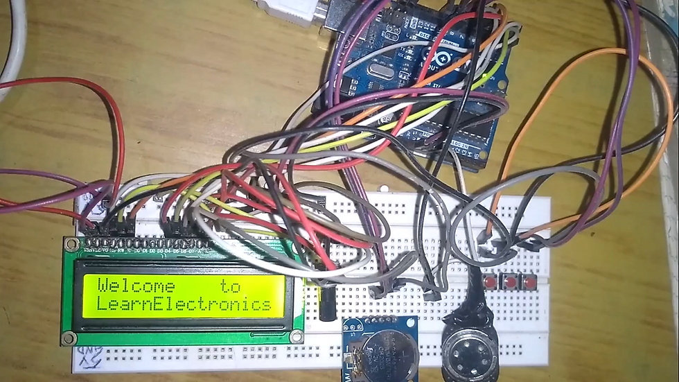
Display welcome message: After a required delay period, print a welcoming message on the LCD display. This provides feedback to the user, indicating that the alarm clock is ready for use.
Concatenate time and date: In the void loop() function, use conditional statements (if condition) to extract integer values representing the time and date from the DS1307RTC.h library. Concatenate these values into a string for displaying the current time and date on the LCD.
Implement the void beep() method: This method sets the buzzer to emit a loud and low sound. Include a suitable delay to control the duration and rhythm of the sound. This ensures that the buzzer responds appropriately when the alarm is triggered.
Working:
Set up the circuit as described, and then upload the code to the Arduino Uno using the Arduino IDE. Adjust the screen's contrast using the potentiometer. To set an alarm, press the first pushbutton an odd number of times. Press it an even number of times to save the alarm. The second push-button increases the hour value by one unit, while the third push-button increases the minutes value by one unit. The buzzer sounds when the alarm goes off.
Check the Project working video here - Arduino Alarm Clock using DS1307 || Arduino Projects
Video By - Maninder Kumar
This project was made using hardware components but we can also make it using simulation platforms like Proteus, tinkercad com
Create more Arduino Projects using tinkercad com by referring to this article. - Top 50 TinkerCAD Projects.
For Tinkercad login assistance, visit tinkercad com
Written by-
Name- Nagashree R Nadig
Portfolio Link- https://www.learnelectronicsindia.com/team/nagashree-r-nadig
See also-


Check out our Free Arduino Projects Playlist - Arduino Projects
Check out our Free Raspberry Pi Projects Playlist - Raspberry Pi Projects
Check out our Free TinkerCAD Projects Playlist - TinkerCAD Projects
Check out our Free IoT Projects Playlist - IoT Projects
Check out our Free Home Automation Projects Playlist - Home Automation Projects
Check out our Free NodeMCu Projects Playlist - NodeMCu Projects
Order Electronics Projects
Want us to guide you through your project or make the project for you? Click on the button below or reach out to us via Call/WhatsApp at (+91) - 7600948607
You can -
Order Basic Electronics Projects
Order Embedded Systems Projects
Order IoT Projects
Order FPGA Projects
Order VLSI Projects
Order Image Processing Projects
Order Matlab Projects
Order TinkerCAD Projects
Order Proteus Projects
Click on the button below to fill out the project inquiry form -
Create Various Projects
Check out our Free Arduino Projects Playlist - Arduino Projects
Check out our Free Raspberry Pi Projects Playlist - Raspberry Pi Projects
Check out our Free TinkerCAD Projects Playlist - TinkerCAD Projects
Check out our Free IoT Projects Playlist - IoT Projects
Check out our Free Home Automation Projects Playlist - Home Automation Projects
Check out our Free NodeMCu Projects Playlist - NodeMCu Projects
Follow us -
Please do follow us i.e. #learnelectronicsindia to get daily updates about new blogs, videos, courses, products, offers, competitions, quizzes, and Internship Opportunities.
Informative and concise! LearnElectronics India always delivers quality content.
Wow, this Arduino Alarm Clock tutorial is incredible! The step-by-step instructions provided by Learn Electronics India are so clear and easy to follow. I never thought I could build my own alarm clock, but this guide made it possible. Thank you for sharing this informative and inspiring blog.
Hello, I cannot figure out how to see/set the time or alarm. Do I have to input anything in the code? Thank you