
Thyristor - It's working, types and applications
- Bhavya Putta
- Feb 23, 2021
- 8 min read

Updated: Jan 28, 2025

Studies have revealed that for transmitting voltages of very high magnitude over large distances, #HVDC(High voltage Direct Current) transmission is more economical. So, there is a necessity to convert the generated high voltage AC in the power generation stations to high voltage DC. A thyristor seems to be capable of doing this effectively, even at high voltages and currents. It is a four-layered, 3 terminal solid-state semiconductor device that can act as a bistable switch, rectifier, and many more. Let's get to know in detail about this compact and compelling device.
What is a thyristor?
If a power supply is connected to a normal transistor, one of the two junctions between the P and N layers will be reverse biased. Thus, a continuous secondary voltage is connected between the emitter and base terminals to bring the transistor into the ON state. But, this secondary voltage source means high power loss, particularly for high power applications.
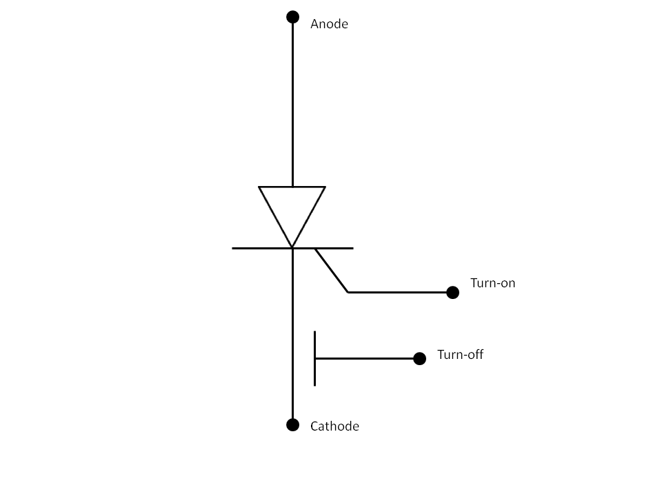
As a solution to this, William Shockley proposed the thyristor for the first time in 1950. The name Thyristor is a blend of THYRatron and transISTOR. It can operate even after disconnecting the secondary voltage source. It is basically a semiconductor device that has 4 alternate P and N layers. The basic form of a thyristor has three terminals named Cathode, Anode, and Gate. The gate terminal is connected to the P-layer near the cathode. It controls the flow of charges between the anode and cathode terminals.

How does Thyristor work?
To understand the working of a thyristor, let's know in brief about the diodes. In a diode, two semiconductor materials, one doped with P-type impurities and the other with N-type impurities are joined to form a PN junction. At the junction, there forms a depletion layer due to the initial migration of electrons and holes, thereby restricting the further movement of charge carriers across the junction. The potential developed across the junction due to the initial migration of charge carriers is the Barrier potential.

When a voltage source greater than the barrier potential is connected across the diode, the charge carriers overcome the block and the diode starts conducting. This is termed as the forward bias. When the polarity of the voltage source connected across the diode is reversed, the charge carriers move further away from the junction and no conduction takes place. This state is recognized as a reverse bias.
Coming to the thyristor, four alternate P and N layers of semiconductors are joined. Consider a P-N-P-N #thyristor connected to a voltage source. In this case, at least one of the three junctions(the middle junction) of the thyristor would be reverse biased. To make the device conducting, the depletion region should be broken down. This is achieved using the Gate-enabling process.

A secondary voltage source is connected between the gate and cathode terminal and electrons are injected into the P-region. Eventually, the P-region becomes flooded with electrons and becomes an N-region. The bottom three layers are now N-type and the topmost layer is P-type. Thus, it functions as a PN junction diode and starts conducting and continues to conduct even if the secondary voltage source is removed. This is because sufficient #electrons are injected into the P-region and they have made their way into the N-region.
Thus, when a sufficient positive signal pulse or #current is given to the gate terminal of a thyristor, it starts conducting. The minimum value of current known as Holding current (Ih) is necessary to operate the thyristor in ON state. At the #semiconductor level, for the thyristor to turn ON (or latch on) and start conducting, the sum of current gains of both the common base transistors must exceed unity. The current so required is known as the Latching current.
How to switch off the thyristor?
To switch off a thyristor, the value of current through it must be changed, so that the sum of current gains is less than one. Turn off begins after the value of the current becomes less than the Holding current. They can also be switched off by connecting them in a tuned LC circuit, where they are subjected to fluctuating voltage instead of steady voltage.
Switching characteristics

By giving the power supply, we obtain the V-I characteristics between the cathode voltage Va and anode current Ia. From the characteristics obtained, it is inferred that the thyristor can have three modes of operation. They are
Reverse Blocking Mode:

In this mode, the cathode is made slightly positive with respect to the anode. The secondary voltage source is not connected. Thus, junctions 1 and 3 are reverse biased, and junction 2 is forward biased. The thyristor behaves as two diodes connected in series with a reverse voltage source connected to them. Only a small leakage current of the order of microamperes flows through the device. This is the OFF condition of the thyristor.
When the reverse voltage applied exceeds a certain threshold called the breakdown voltage, an avalanche occurs at the reverse-biased junctions, and the current increases rapidly. This may cause excessive heating and damage to the device. Thus, the reverse working voltage of the device should be less than the breakdown voltage(Vbr). In reverse blocking mode, the thyristor offers high reverse impedance and thus can be treated as an open circuit.
Forward Blocking Mode:

In this mode, the anode is positive compared to the cathode. The switch to the gate terminal is kept open. Subsequently, junctions 1 and 3 become forward biased, and junction 2 becomes reverse biased. A small value of initial forward leakage current flows from anode to cathode with a tiny voltage drop across the terminals. The impedance offered is very high, and hence the device acts as an open circuit in this case too.
Forward Conduction Mode:
The thyristor can be drawn to forward conduction mode from the forward blocking mode by connecting a suitable gate pulse between the gate and cathode terminals. In this mode, the thyristor conducts maximum current at a minimum voltage and is said to be in the ON state.
Classification of Thyristors
Thyristors can be classified depending on their turn on and turn off capability and V-I characteristics. The flowchart shown below depicts the classification of thyristors. Let's apprehend each of them in detail.

Thyristors with turn-on capability
Silicon Controlled Rectifier(SCR):

SCRs are the most common thyristors known. They can conduct even after the gate pulse is removed. Their characteristics are ideal for phase control. They are employed in switching circuits, static switches, inverters, and DC motor drives.
Reverse Conducting Thyristor (RCT):
Usually, the thyristors conduct only in the forward mode, blocking any reverse currents. But in an RCT, an SCR is integrated with a reverse diode to remove unnecessary loop inductances and voltage transients. RCT can conduct even in the reverse mode with decent commutation. These are deployed in inverter circuits and DC drives of high power choppers.
Light-Activated Silicon-Controlled Rectifier (LASCR):

They are also known as light-triggered thyristors(LTT). In these devices, the number of electron-hole pairs in the reverse-biased junction increases when light particles strike the junction. They are used in HVDC transmission, High voltage pulse generators, and power compensators.
Thyristors with turn-off capability
For the thyristors discussed above, they can be switched on using a suitable gate pulse. But to switch off them, the supply current has to be interrupted as the current doesn't become zero naturally. This inconvenience can be subdued by using the thermistors with turn-off capacity.
Gate Turn-off Thyristor (GTO):

They are also referred to as Gate-Controlled Switches(GCS) because they can be switched off easily by reversing the polarity of the gate current. It can be switched off 10 times faster than the SCR. GTO's are used in high power inverters, DC and AC motor drives.
MOS Turn-off Thyristor (MTO):
In an MTO, a GTO is connected with a MOSFET to improve the switch-off time even further. To turn off an MTO, a voltage pulse is given to the MOSFET. It shorts the emitter and base of the NPN transistor, thereby stops latching. They are used in motor drives, flexible AC line transmissions(FACTs), and high voltage applications up to 20 MVA.
Emitter Turn-off Thyristor (ETO):
It is similar to an MTO, except for the second gate terminal connected in series with the MOSFET. To turn off the ETO, a negative voltage pulse is applied to the #MOSFET. The NMOS turns off and transfers all the charge away from the cathode, thus latching stops. They are used in high voltage inverters, static synchronous compensators(STATCOM), and flexible AC line transmissions(FACTs).
Bidirectional Control
To use thyristors for AC voltage control, two circuits must be connected in anti-parallel resulting in two control circuits. This increases the complexity and number of wires. Thus, bidirectional control thyristors that can conduct in both directions when triggered are developed.
Triode for Alternating current (TRIAC):

#TRIAC is a five-layered device. These are the second-most widely used thyristors after the SCR's. They allow bidirectional current flow thus providing control over both the halves of the alternating waveform. These are generally used only for low power applications as they have significant disadvantages in high power applications due to their unsymmetrical nature. They are used in speed control of various appliances and as light dimmers.
Diode for alternating current (DIAC):

These are usually used in combination with TRIACs. They are connected in series with the gate terminal of TRIAC. The DIACs doesn't allow the flow of current through TRIAC until a particular voltage level is reached in the DIAC, thus enabling symmetric triggering in either direction. They are commonly used in light dimmers.
Silicon Diode for Alternating Current (SIDAC):

They are quite similar to the DIACs except that SIDACs have a higher voltage capacity and can be directly used as switches instead of using them as triggers for other devices. They are used in many special-purpose devices such as Relaxation Oscillators.
Applications of Thyristors
A few applications of thyristors are listed here:
They are primarily used in HVDC transmission.
They are used for switching and rectification at very high voltages and currents.
They are used as control elements in phase fired controllers.
Used as power supplies in digital circuits.
They are used as enhanced circuit breakers to prevent a failure from damaging the other components of the power system.
Thyristors with a Zener diode connected to its gate terminal are used as crowbars. A crowbar is more advantageous than a conventional circuit breaker or fuse.
The first large scale application of thyristors was in the theatre, television, and motion picture.
They have replaced rheostats and autotransformers in many applications.
They are critical parts of flashes and are also used in photography.

Conclusion
Although thyristors are used in high voltage AC to DC rectification, low and medium voltages are rectified using other superior rectifiers such as power MOSFETs. MOSFETs also replace thyristors in high-frequency applications because thyristors have a longer switching time due to bipolar conduction.
However, when it comes to the handling of high voltages and currents, thyristors can withstand up to 6000 V and 4500 A. They can rapidly switch between the states of conduction and non-conduction. In addition to all its advantages, its maintenance cost is low and it can operate without fault for many years under proper conditions of the environment.
See Also
Superconductors
O
rder Electronics Projects
Want us to guide you through your project or make the project for you? Click on the button below or reach out to us via Call/WhatsApp at (+91) - 7600948607
You can -
Order Basic Electronics Projects
Order Embedded Systems Projects
Order IoT Projects
Order FPGA Projects
Order VLSI Projects
Order Image Processing Projects
Order Matlab Projects
Order TinkerCAD Projects
Order Proteus Projects
Click on the button below to fill out the project inquiry form -
Create Various Projects
Check out our Free Arduino Projects Playlist - Arduino Projects
Check out our Free Raspberry Pi Projects Playlist - Raspberry Pi Projects
Check out our Free TinkerCAD Projects Playlist - TinkerCAD Projects
Check out our Free IoT Projects Playlist - IoT Projects
Check out our Free Home Automation Projects Playlist - Home Automation Projects
Check out our Free NodeMCu Projects Playlist - NodeMCu Projects
Follow us -
Please do follow us i.e. #learnelectronicsindia to get daily updates about new blogs, videos, courses, products, offers, competitions, quizzes, and Internship Opportunities.
LearnElectronics India's explanation is spot-on. Great work!
Learn Electronics India never fails to impress, and this blog post on Thyristors is no exception! The way they delved into the intricacies of Thyristor operation and the different types showcased their deep understanding of the subject matter. I particularly appreciated the practical examples they provided, which really helped me connect the theoretical concepts to real-world scenarios. This blog has become my go-to resource for electronics education, and I can't wait to see what they have in store for us next. Highly recommended.