


Arduino UNO based Memory Game
Introduction
Memory games are an excellent way to learn embedded systems and Arduino programming because they combine multiple hardware and software concepts into a single interactive application. This project demonstrates LCD interfacing, keypad input handling, random number generation, sound feedback using a buzzer, and EEPROM data storage while creating an enjoyable game for the user.
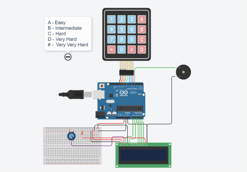
In this project, an Arduino UNO is used to implement a Memory Game in which the player must remember and reproduce a sequence of randomly generated numbers displayed on a 16×2 LCD. The sequence becomes longer with each successful level, increasing the difficulty of the game. The player has three lives, and the game ends when all lives are exhausted.
The project also includes multiple difficulty levels that control how long each number is displayed, making the game suitable for beginners as well as experienced players. Additionally, the highest score is stored in the Arduino's EEPROM memory so that it is retained even after the system is powered off.
By developing this project, beginners can gain practical experience with Arduino programming, LCD interfacing, keypad communication, EEPROM usage, and real-time game logic while building an engaging embedded system application.
What You'll Learn
By completing this project, you will learn:
How to interface a 16×2 LCD module with an Arduino UNO using the LiquidCrystal library.
How to interface and read inputs from a 4×4 matrix keypad using the Keypad library.
How to generate random number sequences using Arduino's built-in random number functions.
How to provide audio feedback using a buzzer for correct and incorrect responses.
How to implement multiple difficulty levels by controlling the sequence display time.
How to use the Arduino's EEPROM to permanently store the highest score.
How to develop an interactive memory game using user input validation and game logic.
Components Required
Component | Quantity | Purpose |
Arduino UNO | 1 | Acts as the main controller that executes the game logic, processes keypad inputs, controls the LCD, buzzer, and EEPROM operations. |
16×2 LCD Module | 1 | Displays the welcome screen, difficulty selection, random sequence, game status, level, and high score. |
4×4 Matrix Keypad | 1 | Allows the player to select the difficulty level and enter the displayed number sequence. |
Piezo Buzzer | 1 | Provides audio feedback during sequence display and for correct or incorrect answers. |
10 kΩ Potentiometer | 1 | Adjusts the contrast of the 16×2 LCD for proper visibility of characters. |
220 Ω Resistor | 1 | Limits the current supplied to the LCD backlight, protecting it from excessive current. |
Breadboard | 1 | Provides a platform for assembling the circuit without soldering. |
Jumper Wires | As Required | Connect the Arduino with the LCD, keypad, buzzer, and other components. |
USB Cable | 1 | Powers the Arduino and uploads the program from the computer. |
Project Overview
The Arduino Memory Game is an interactive embedded systems project that challenges the player's memory by displaying a sequence of random numbers on a 16×2 LCD. The player must carefully observe the displayed sequence and then reproduce it using a 4×4 matrix keypad. As the game progresses, the sequence becomes longer, making each level more challenging than the previous one.

When the game starts, the player is welcomed with a start screen and prompted to select a difficulty level. Five difficulty levels are available, each controlling how long the numbers remain visible on the LCD before disappearing. This allows the game to be played by both beginners and experienced users with different skill levels.
The player begins with three lives. Each correct answer advances the player to the next level, while an incorrect answer reduces the remaining lives by one. Audio feedback is provided through a piezo buzzer for both correct and incorrect responses, making the gameplay more interactive. Once all lives are lost, the game displays the final level reached along with the highest score achieved.
To enhance the gaming experience, the highest score is stored in the Arduino's built-in EEPROM memory. This allows the high score to remain saved even after the Arduino is powered off or restarted. By combining LCD interfacing, keypad communication, EEPROM storage, sound generation, and game logic, this project provides an excellent example of a complete Arduino-based embedded system application.
Circuit Diagram
The Memory Game circuit is built around the Arduino UNO, which acts as the central controller for the entire system. A 16×2 LCD is interfaced with the Arduino using the LiquidCrystal library to display the game interface, including the welcome screen, difficulty selection, generated number sequence, user prompts, game status, and high score.
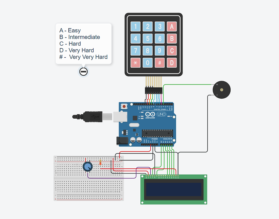
A 4×4 matrix keypad is connected to the Arduino to allow the player to select the game difficulty and enter the displayed number sequence. A piezo buzzer is included to provide audio feedback during gameplay by generating different tones for sequence display, correct answers, and incorrect answers.
The circuit also includes a 10 kΩ potentiometer to adjust the LCD contrast for better character visibility and a 220 Ω resistor to limit the current supplied to the LCD backlight. All components are assembled on a breadboard using jumper wires, creating a simple and organized embedded system suitable for simulation as well as hardware implementation.
Circuit Connections
Component | Arduino Connection | Purpose |
LCD RS | Analog Pin A0 | Selects whether the LCD receives a command or displays data. |
LCD Enable (E) | Analog Pin A1 | Enables communication between the Arduino and the LCD. |
LCD Data Pin D4 | Analog Pin A2 | Transfers data to the LCD in 4-bit mode. |
LCD Data Pin D5 | Analog Pin A3 | Transfers data to the LCD in 4-bit mode. |
LCD Data Pin D6 | Analog Pin A4 | Transfers data to the LCD in 4-bit mode. |
LCD Data Pin D7 | Analog Pin A5 | Transfers data to the LCD in 4-bit mode. |
LCD GND | GND | Provides the ground reference for the LCD. |
LCD VCC | 5V | Supplies power to the LCD module. |
LCD RW | GND | Keeps the LCD in write mode. |
LCD VO | 10 kΩ Potentiometer | Adjusts the LCD contrast. |
LCD LED+ | 5V through a 220 Ω resistor | Powers the LCD backlight safely. |
LCD LED− | GND | Completes the LCD backlight circuit. |
Keypad Row Pins | Digital Pins 12, 11, 10, 9 | Used by the Arduino to scan the keypad rows. |
Keypad Column Pins | Digital Pins 8, 7, 6, 5 | Used by the Arduino to detect key presses. |
Piezo Buzzer (+) | Digital Pin 4 | Generates sound effects during gameplay. |
Piezo Buzzer (−) | GND | Completes the buzzer circuit. |
Working of the Connections
The Arduino UNO serves as the central controller of the Memory Game. It continuously communicates with the 16×2 LCD, 4×4 keypad, and piezo buzzer to manage the gameplay. The LCD is interfaced in 4-bit mode, reducing the number of I/O pins required while still allowing the Arduino to display text, numbers, and game messages efficiently.
The 4×4 matrix keypad acts as the primary input device. It allows the player to select the desired difficulty level and enter the displayed number sequence during the game. The Arduino continuously scans the keypad rows and columns to detect key presses and validate the player's input against the generated sequence.
The piezo buzzer provides audio feedback throughout the game. A short beep is produced whenever a number is displayed, another sound confirms each key press, a success melody is played when the player correctly reproduces the sequence, and a different tone indicates an incorrect answer. These sound effects make the game more interactive and improve the overall user experience.
The 10 kΩ potentiometer is used to adjust the contrast of the LCD, ensuring that the displayed characters remain clearly visible under different viewing conditions. The 220 Ω resistor limits the current supplied to the LCD backlight, protecting it from excessive current and improving its reliability.
By working together, these hardware components enable the Arduino to generate random number sequences, accept user responses, provide visual and audio feedback, manage the game state, and store the highest score in the built-in EEPROM memory.
Source Code
The complete Arduino program for the Arduino Memory Game is provided below.
You can download the complete Arduino source code for this project using the download option provided below.
Code Explanation
Library Inclusion and Global Variable Declaration


The program begins by including the LiquidCrystal, Keypad, and EEPROM libraries, which provide the functions required to interface with the 16×2 LCD, 4×4 matrix keypad, and the Arduino's built-in EEPROM memory, respectively.
An LCD object is created by specifying the Arduino pins connected to the display, while the keypad layout and its corresponding row and column pins are configured using the Keypad library. This configuration enables the Arduino to detect key presses accurately during gameplay.
Several global variables are declared to manage the game's operation. These variables store the generated number sequence, the player's input, the current level, the remaining lives, the highest score, and the sequence display duration. Keeping these variables global allows different functions in the program to access and update the game state whenever required.
setup() Function

The setup() function is executed only once when the Arduino is powered on or reset. It initializes all the hardware components and prepares the Memory Game before gameplay begins.
First, the LCD is initialized as a 16×2 display, and the buzzer pin is configured as an output so that the Arduino can generate audio feedback during the game. The random number generator is then seeded using an analog input to ensure that a different number sequence is generated each time the game starts.
Next, the previously saved high score is read from the Arduino's built-in EEPROM, allowing the highest score to be retained even after power is removed. Finally, the welcomeScreen() function is called to display the game's welcome message and wait for the player to start the game.
loop() Function


The loop() function is the main execution cycle of the program and runs continuously while the Arduino is powered. At the beginning of each game, it calls the selectDifficulty() function, allowing the player to choose one of the available difficulty levels. The game variables are then initialized by setting the starting level to 1 and the number of lives to 3.
The game continues inside a while loop as long as the player has at least one remaining life. During each level, a random number sequence is generated and displayed on the LCD. The player's response is then collected through the keypad and compared with the generated sequence to determine whether the answer is correct.
If the player enters the correct sequence, a success sound is played, the high score is updated in the EEPROM whenever a new record is achieved, and the game advances to the next level. If the entered sequence is incorrect, the remaining lives are reduced by one, an error sound is played, and the LCD displays the updated number of lives. Once all lives are exhausted, the gameOver() function is called to display the final results and restart the game.
welcomeScreen() Function

The welcomeScreen() function displays the initial screen when the game starts. It clears the LCD and shows the title "MEMORY GAME" along with the message "Press #", prompting the player to begin the game.
The function continuously monitors the keypad inside an infinite while loop. It waits until the player presses the '#' key before exiting the function and allowing the game to continue. This ensures that the game begins only after the player is ready.
selectDifficulty() Function


The selectDifficulty() function allows the player to choose the game's difficulty level before each new game begins. The LCD displays the message "Choose Difficulty", and the program continuously waits for a valid key press from the keypad.
Five difficulty levels are available. Pressing A, B, C, D, or # sets different values for the displayTime variable, which controls how long each number in the generated sequence remains visible on the LCD. Lower display time increase the game's difficulty by giving the player less time to memorize each number.
After a valid difficulty level is selected, the LCD displays the "Starting..." message for one second before the gameplay begins.
generateSequence() Function

The generateSequence() function creates a random sequence of digits for the current game level. It receives the required sequence length as a parameter and uses a for loop to generate one random digit at a time.
Each digit is generated using the random() function, which produces a value between 0 and 9. The generated number is then converted into its corresponding character before being stored in the sequence array. The completed sequence is later displayed on the LCD and used to verify the player's input.
showSequence() Function

The showSequence() function displays the randomly generated number sequence to the player, one digit at a time. It first clears the LCD, displays the current level number, and pauses briefly before showing the sequence.
A for loop is then used to display each digit stored in the sequence array. Every number is shown at the center of the LCD for a duration determined by the selected difficulty level (displayTime). At the same time, the buzzer produces a short beep to draw the player's attention to each displayed digit. After each digit is shown, the LCD is cleared before displaying the next one, making the sequence easier to observe.
Once the complete sequence has been displayed, the LCD shows the message "Your Turn" for one second before clearing the screen and allowing the player to enter the memorized sequence using the keypad.
getAnswer() Function

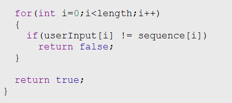
The getAnswer() function is responsible for collecting the player's input and verifying whether it matches the generated number sequence. It receives the required sequence length as a parameter and displays the message "Enter:" on the LCD, prompting the player to input the memorized sequence using the keypad.
The function continuously waits for key presses until the required number of digits has been entered. Only numeric keys (0–9) are accepted as valid inputs. Each entered digit is stored in the userInput array, while an asterisk (*) is displayed on the LCD instead of the actual number to indicate that a key has been pressed. A short beep is also generated through the buzzer to provide immediate feedback for every valid key press.
After the complete sequence has been entered, the function compares each digit in the userInput array with the corresponding digit in the sequence array. If any mismatch is found, the function immediately returns false, indicating an incorrect answer. If all the entered digits match the generated sequence, the function returns true, allowing the player to proceed to the next level.
correctSound() Function

The correctSound() function generates a success melody whenever the player correctly reproduces the displayed number sequence. It plays three tones of increasing frequency through the piezo buzzer, with short delays between them to create a pleasant confirmation sound. This audio feedback informs the player that the answer is correct and the game will proceed to the next level.
wrongSound() Function
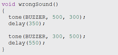
The wrongSound() function generates an error tone whenever the player enters an incorrect sequence. It plays two tones of decreasing frequency through the buzzer with appropriate delays, producing a distinct sound that indicates an incorrect answer. This feedback helps the player immediately recognize the mistake before the remaining lives are updated.
gameOver() Function

The gameOver() function is executed when the player loses all three lives. It clears the LCD and displays the "GAME OVER" message along with the level reached during the game. After a short delay, the LCD is cleared again to display the highest score stored in the Arduino's built-in EEPROM memory.
Once the final information has been displayed, the function calls the welcomeScreen() function, allowing the player to return to the start screen and begin a new game. Since the high score is stored in EEPROM, it remains available even after the Arduino is powered off or restarted.
Simulation Output
The Memory Game was successfully simulated in Tinkercad, where all the game functionalities operated as expected. After powering on the Arduino, the LCD displayed the welcome screen and waited for the player to press '#' before starting the game. The player could then select one of the available difficulty levels using the 4×4 keypad.

The game correctly generated and displayed a random number sequence one digit at a time on the LCD. The player entered the memorized sequence using the keypad, while each key press was represented by an asterisk (*) on the display to hide the entered digits. Audio feedback was also produced through the piezo buzzer during gameplay.
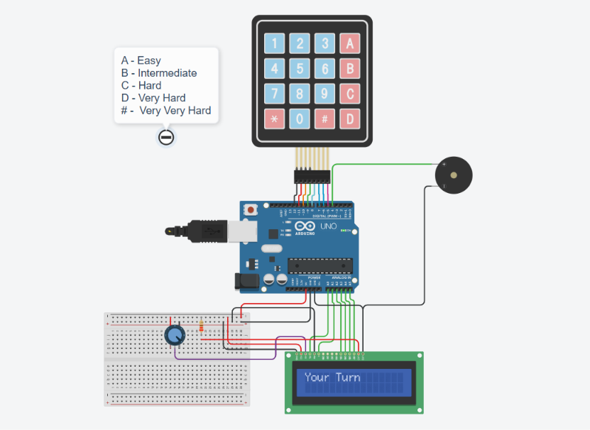
Whenever the entered sequence matched the generated sequence, the game advanced to the next level and increased the sequence length, making the gameplay progressively more challenging. If an incorrect sequence was entered, the remaining lives decreased, and once all lives were exhausted, the LCD displayed the GAME OVER message followed by the highest score stored in EEPROM memory.

The simulation confirmed the correct implementation of LCD interfacing, keypad communication, EEPROM-based high-score storage, random sequence generation, sound feedback, and overall game logic, demonstrating the successful operation of the Arduino Memory Game.
Video Demonstration
Applications
Learning Arduino programming through an interactive memory-based game.
Understanding LCD interfacing using the LiquidCrystal library.
Demonstrating keypad interfacing and user input processing.
Learning EEPROM data storage for retaining information after power loss.
Teaching embedded system concepts such as random number generation, game logic, and sound generation.
Mini projects for students, hobbyists, and Arduino beginners.
Embedded systems laboratory demonstrations and workshops.
Advantages
Beginner-friendly embedded systems project.
Uses inexpensive and easily available electronic components.
Demonstrates multiple Arduino programming concepts in a single project.
Improves understanding of LCD interfacing, keypad communication, and EEPROM memory.
Interactive gameplay with adjustable difficulty levels.
High score is retained even after power is removed.
Easily customizable by adding new game features.
Future Improvements
The Memory Game can be enhanced further by adding additional features such as:
Increasing the maximum number of levels.
Supporting letters and symbols in addition to numeric sequences.
Adding different game modes with varying difficulty rules.
Displaying player statistics such as total games played and average score.
Playing unique sound effects for each keypad button.
Using an RGB LED to provide visual feedback for correct and incorrect answers.
Implementing multiplayer or timed challenge modes.
Conclusion
The Arduino UNO based Memory Game demonstrates how a microcontroller can be used to develop an interactive embedded application by combining a 16×2 LCD, 4×4 keypad, piezo buzzer, and EEPROM memory. The project successfully implements random sequence generation, keypad-based user interaction, adjustable difficulty levels, audio feedback, score tracking, and permanent high-score storage.
This project provides an excellent platform for learning Arduino programming, LCD interfacing, keypad communication, EEPROM usage, and embedded game development. It also serves as a strong foundation for building more advanced memory games and interactive embedded system applications.
Comments