Ripple Counter
- Nagapuri Swathi
- Jun 21, 2021
- 2 min read
Updated: Aug 9, 2023
Counters are sequential circuits that are used to count clock pulses. #Counters are a group of flip-flops to which a clock signal is applied. Counters can be basically classified as #Asynchronous counters and #Synchronous counters. Counters are also classified as up counter, down counter, and up-down counter based on their design.
Up counter:
The counter which counts the states in ascending order is known as the up counter.
Down counter:
The counter which counts the states in descending order is known as the down counter.
Up-Down counter:
The counter that counts in either the direction i.e., in the forward or in the reverse direction is called an Up-Down counter.
Ripple Counter:
Ripple counter is an asynchronous counter. An n-bit ripple counter can count up to 2 to the power of n states, it is also referred to as MOD n counter.
Binary Ripple Counter:
The circuit of the Binary Ripple Counter is shown below.

#Binary Ripple Counter uses 2 flip-flops. The inputs to the flip-flop 1 are J0 and K0 and the inputs to the flip-flop 2 are J1 and K1. The inputs of both the flip-flops are set to high. The output of the first flip flop is given as a #clock to the next flip flop. The #LSB and #MSB are Q0 and Q1 respectively. As both the inputs of the #JK flip-flop are 1 the output will be #toggled to each clock pulse applied.
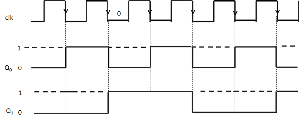
The timing diagram of the Binary Ripple Counter is shown below.

From the timing diagram, it can be observed that the output Q0 changes its state during the negative edge of the applied clock. Initially, the state of the flip-flop is at 0. Flip-Flop remains in this state until the next negative clock pulse is given. The output of the flip-flop toggles from 0 to 1. For all clock pulses, the process continues.
The output of the first flip-flop is given as a clock to the second flip-flop i.e., the output waveform of the first flip-flop acts as a clock to the second one. So we can observe that the state of Q1 changes when the output of the first flip-flop goes from 1 to 0. Thus the counter counts 00, 01, 10, and 11 and resets itself and counts again from 00.

3-bit Ripple Counter using JK flip-flop:
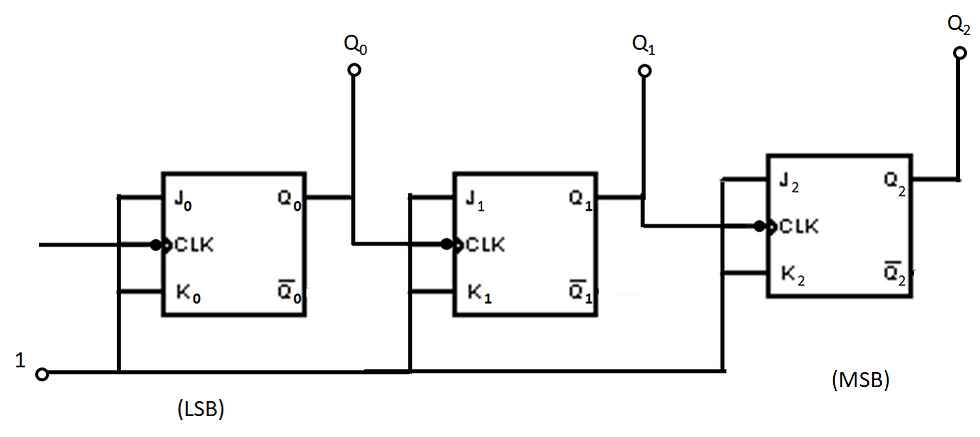
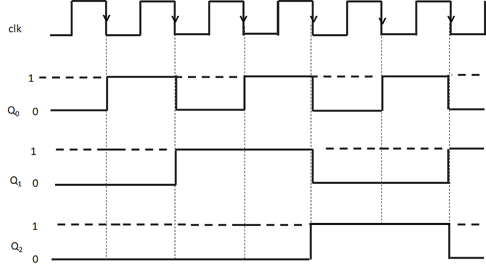
3-bit Ripple Counter uses 3 flip-flops. This counter counts up to 8 states. It is a mod 8 counter.
The following figure shows the 3-bit ripple counter using a flip-flop.

In the circuit above, both the inputs of the JK flip-flop are set i.e., J=K=1. When both J and K are 1 JK flip-flop works in toggle mode. Therefore, for every clock pulse Q0 will toggle. Let the clock be negative edge triggered. So the above circuit acts as an up counter as the output is taken at Q and the clock is negative edge triggered.
The truth table for the 3-bit ripple counter is shown below.

Timing diagram:

See Also:
Follow us -
Please do follow us i.e #learnelectronicsindia to get daily updates about new blogs, videos, courses, quizzes, and contests.
Author -
Written By: Nagapuri Swathi


Clear and concise. LearnElectronics India's expertise shines through.
Thank you, Learn Electronics India, for this outstanding article on Ripple Counters. The clarity and simplicity with which complex concepts are explained are truly praiseworthy. Your blog has become my go-to resource for learning electronics. Keep up the excellent work.